Table of Contents
What Changed in AS/NZS 3008.1.1:2025
AS/NZS 3008.1.1:2025 was published in December 2025 and replaces AS/NZS 3008.1.1:2017 for selecting low-voltage cables in Australia and New Zealand. Seven changes have a direct impact on day-to-day cable sizing: dedicated DC sizing tables, renamed and expanded correction factors with multi-row arrangements, current-carrying capacity (CCC) for 110 °C aluminium conductors, simplified copper CCC tables, additional installation cases for cables in thermal insulation, formal treatment of voltage rise and unbalanced systems, and tabulated short-circuit withstand currents.
This article summarises each change, explains why it matters in practice, and outlines the immediate actions engineers should take. All seven changes are implemented in the free AS/NZS 3008.1.1 Cable Sizing Calculator at elek.com/calculators, and in the full version of ELEK Cable Pro Web™.
Why This Update Matters
AS/NZS 3008.1.1 is the principal reference for selecting cables up to 0.6/1 kV in Australia and New Zealand. Its tables and equations are incorporated into cable schedules, design reports, and software used on every electrical installation — from residential switchboards to utility-scale solar farms.
The 2025 revision is the first major update in eight years. It reflects the rapid growth of DC distribution (battery energy storage, EV charging, large-scale PV), the broader use of 110 °C-rated cable systems, and the need for explicit treatment of generation circuits that allow current to flow in either direction. Engineers using the 2017 edition will find that some calculations are no longer aligned with current best practice — and in several cases, the new tables produce different cable sizes for the same load.
The seven changes below are the ones most likely to affect a cable schedule.
1. Dedicated DC Cable Sizing Tables
The 2017 edition treated DC sizing as a side note, with users effectively re-purposing AC tables. AS/NZS 3008.1.1:2025 introduces a complete set of dedicated DC tables.
- DC current-carrying capacity tables for single-core and multicore cables across all standard installation methods (Tables 3.21 onwards).
- DC conductor resistance tables giving R_c in Ω/km at conductor temperatures from 25 °C to 110 °C (Table 4.6 series).
- DC voltage drop tables providing mV/A·m values for direct use in voltage-drop calculations (Table 4.16 series).
Why it matters: AC and DC current ratings differ because DC has no skin effect, no proximity effect, and no sheath/armour eddy losses. Using AC tables for DC circuits typically oversizes conductors at small sizes and undersizes them at large sizes, where the AC-only loss components previously inflated the apparent rating. The new tables also eliminate the need to manually back out AC-only loss components.
How to apply it: For battery, PV string, EV charging and DC microgrid circuits, use the new DC tables directly. Do not interpolate AC values for DC applications. The AS/NZS 3008.1.1 calculator on elek.com/calculators automatically selects the DC tables when a DC supply is specified.

2. Correction Factors — Renamed and Expanded for Multi-Row Groups
The terminology has changed: what AS/NZS 3008.1.1:2017 called the derating factor is now formally the correction factor. This aligns the standard with IEC 60364-5-52 and removes the implication that the factor always reduces ampacity (it can also increase it for spaced or favourable installations).
The bigger practical change is that the correction-factor tables now cover multi-row cable groups. The 2017 edition only tabulated single-row arrangements; multi-row installations had to be approximated by combining a single-row factor with engineering judgement. The 2025 edition adds dedicated tables — for example:
- Table 3.37 — single-core cables buried direct in the ground, multiple rows.
- Table 3.39 — multicore cables buried direct in the ground, multiple rows.
- Table 3.41 — single-core cables in separate underground enclosures, multiple rows.
- Table 3.43 — single-core or multicore cables in underground enclosures, multiple rows.
Each table is indexed by the number of circuits (3, 4, 6, 9, 12) and centre-to-centre distance S between circuits (typically 0.15 m, 0.30 m, 0.45 m, 0.60 m).
Why it matters: Multi-row trench arrangements are common in industrial and renewable installations — a single multi-circuit trench feeding a switchboard, an MV reticulation in a solar farm, or a battery DC bus. The 2017 approach systematically over-derated these installations, leading to oversized cables.
How to apply it: Select the correction-factor table that matches the actual installation geometry — direct-buried versus enclosure, single-core versus multicore, single-row versus multi-row — and read the factor at the actual circuit spacing. Spreadsheet tools and calculators must be updated to reference the new tables.

3. Current-Carrying Capacity for 110 °C Aluminium Conductors
The 2017 edition included CCC tables for 110 °C copper conductors but treated 110 °C aluminium as a gap. The 2025 edition closes this gap by providing full CCC tables for R-HF-110, R-E-110, and X-HF-110 insulated cables with aluminium conductors.
The new tables cover the complete installation matrix already used for copper:
- Unenclosed — spaced, spaced from a surface, touching, exposed to sun.
- Enclosed in conduit — metallic and PVC.
- Surrounded by thermal insulation, partially and completely.
- Buried direct in the ground.
- Buried in PVC underground conduit.
Conductor sizes from 1 mm² to 630 mm² are included.
Why it matters: Aluminium is increasingly used at 110 °C operating temperature in long sub-mains, large solar farm DC and AC trunk runs, and utility-scale battery systems. Until now, designers had to interpolate from 90 °C aluminium tables and manually scale for the higher operating temperature, which is error-prone. Direct table values eliminate that ambiguity.
How to apply it: When the cable specification calls for an X-HF-110, R-HF-110 or R-E-110 aluminium conductor, use the new 2025 tables directly rather than interpolating from 90 °C values.

4. Simplified Copper CCC Tables — Stranded and Flexible Combined
In the 2017 edition, copper CCC tables had separate columns for solid/stranded and flexible conductors, despite the difference between them being negligible at most sizes. The 2025 edition merges these into a single column per installation method.
Why it matters: This is a usability and consistency improvement. Two parallel columns invited transcription errors and forced unnecessary decisions for cables where conductor flexibility had no measurable impact on rating. The merged column also makes the tables easier to reference quickly during design reviews.
How to apply it: No conversion is required for existing designs — the values in the merged column are equivalent to the previous solid/stranded column. Update spreadsheets and reference sheets to point at the new column structure.

5. Expanded Cable Installation Cases — Thermal Insulation in Conduits
Several entries that were left blank or marked “—” in the 2017 tables are now populated. The most notable additions are CCC values for cables installed inside conduits that are themselves partially or completely surrounded by thermal insulation — a common situation in modern domestic and commercial buildings using high-performance wall insulation.
The new values appear in the standard CCC matrix (columns 11–14 of Tables 3 and 4 series), covering:
- Conductors in metallic conduit in air.
- Conductors in PVC conduit surrounded partially by thermal insulation.
- Conductors in PVC conduit are surrounded completely by thermal insulation.
Both copper and aluminium, single-core and multicore, are included.
Why it matters: Thermal insulation around a conduit dramatically reduces heat dissipation. Previously, designers had to apply a coarse insulation derating to an air-installed value, which both under-utilised cable and produced inconsistent results between designers. Tabulated values give a single defensible answer.
How to apply it: For circuits passing through insulated walls or ceilings — particularly in passive-house and high-energy-efficiency builds — read the CCC directly from the new “surrounded by thermal insulation” columns. The reduction is significant; an unsuitable cable selected from the air-installed column may exceed its temperature limit in service.

6. Voltage Rise and Unbalanced Systems
The 2025 edition formally addresses two cases that the 2017 edition handled only implicitly.
Voltage rise. For circuits that export power back to the source — typically PV inverter, battery and generator circuits — the same conductor impedance that causes voltage drop under load causes a voltage rise under export. AS/NZS 3008.1.1:2025 includes:
- A formal definition of voltage rise.
- Worked examples for generator and export circuits.
- Guidance on the limits to apply (the AS/NZS 4777.1 grid-connection requirements still govern at the inverter terminals; AS/NZS 3008.1.1 governs the cable contribution).
Unbalanced systems. The 2017 edition’s voltage-drop method assumed balanced multiphase loads. The 2025 edition adds explicit guidance for unbalanced multiphase voltage drop using vector (phasor) addition — relevant where single-phase loads are distributed unevenly across phases, as in many residential and small commercial installations.
Why it matters: Voltage-rise compliance is the most common cause of PV inverter trips on rural and long sub-main connections. Without a standardised method, designers used a mix of conservative but arbitrary 2% targets and bespoke calculations that were difficult to defend in audits. A formal method in the standard provides a single reference.
How to apply it: For any export circuit (PV, BESS, generator), include a voltage-rise calculation alongside the conventional voltage-drop calculation, using the worked-example method in the 2025 edition. For unbalanced installations, replace the simple algebraic voltage-drop sum with the vector addition method now described in the standard. The AS/NZS 3008.1.1 calculator on elek.com/calculators implements both calculations.
7. Tabulated Short-Circuit Withstand Currents
The previous edition required the user to compute short-circuit withstand current from the cable adiabatic equation each time. The 2025 edition adds Table 5.5 — Calculated short-circuit current limit, providing tabulated values for:
- Thermoplastic insulated cables (PVC).
- X-90, X-90UV, X-HF-90, R-EP-90, R-CPE-90, R-HF-90, R-CSP-90.
- X-HF-110, R-HF-110, R-E-110.
Values are given for both copper and aluminium conductors across the full range of standard sizes, in kA.
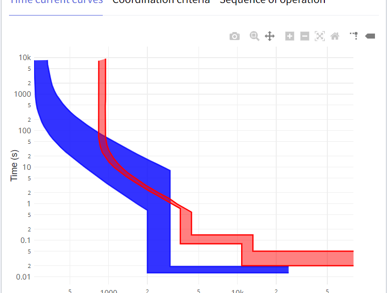
Why it matters: Short-circuit withstand is the constraint that determines whether the cable will survive the time taken by the upstream protective device to clear a fault. Tabulated values let designers verify protection coordination at a glance, rather than recalculating the adiabatic limit for every cable.
How to apply it: During protection coordination, read the cable’s short-circuit current limit from Table 5.5 at the relevant disconnection time (usually 0.1 s, 0.2 s or 1.0 s) and confirm it is greater than the prospective fault current at the cable’s location, multiplied by the protection clearing time factor.

What Should Engineers Do Next?
AS/NZS 3008.1.1:2025 was published in December 2025. Future cable sizing should follow the new edition. The four immediate actions are:
- Use the new DC cable sizing tables for any DC circuit (PV, BESS, EV, DC microgrid). Stop substituting AC values.
- Apply multi-row cable grouping correction factors for any installation with stacked circuits — these are now tabulated and should not be approximated.
- Use the simplified copper CCC tables with the merged stranded/flexible column. Update any in-house spreadsheet references.
- Perform voltage-rise calculations for each export circuit, in addition to the conventional voltage-drop calculation.
Software, spreadsheets, design templates and internal training material that reference the 2017 edition should be reviewed and updated. Cable schedules issued after the transition date should cite AS/NZS 3008.1.1:2025.
The free AS/NZS 3008.1.1 Cable Sizing Calculator at elek.com/calculators has been updated to the 2025 edition and can be used to verify hand calculations or replace legacy spreadsheets immediately.
Key Engineering Takeaways
- AS/NZS 3008.1.1:2025 was published in December 2025 and replaces the 2017 edition for LV cable selection in Australia and New Zealand.
- The most consequential changes for day-to-day design are the dedicated DC tables, the multi-row correction factors, and the formal voltage-rise method for export circuits.
- The 110 °C aluminium CCC tables remove the previous interpolation step for high-temperature aluminium designs.
- Tabulated short-circuit withstand currents (Table 5.5) and the populated thermal-insulation installation cases make routine checks faster and more defensible.
- Terminology has shifted from “derating factor” to “correction factor”, aligning with IEC 60364-5-52.
- In several cases — particularly multi-row trenches and DC circuits — the new tables yield a different (and often smaller) cable size for the same load.
Frequently Asked Questions
When does AS/NZS 3008.1.1:2025 take effect?
AS/NZS 3008.1.1:2025 was published by Standards Australia / Standards New Zealand in December 2025. It is the current edition for new design work. The 2017 edition remains the version cited on legacy projects until those projects are reissued under the new edition. Local regulatory transition dates may apply — check with the relevant electrical regulator in your state or region.
Do I need to redesign existing cable schedules to the 2025 edition?
No. Existing installations remain compliant under the edition they were designed against. New design work, design reviews and cable schedules issued after the transition date should use the 2025 edition. Where an existing design is being modified or extended, the modification should be sized to the current edition.
Why did “derating factor” become “correction factor”?
The new term is consistent with IEC 60364-5-52 and is technically more accurate. A “correction factor” can be greater than, equal to, or less than 1, depending on whether the installation conditions are worse or better than the reference condition. The previous term “derating factor” implied that the factor always reduced ampacity, which is not always correct (for example, spaced single-core cables in air can have a correction factor greater than 1 compared to touching).
Can I still use AC current-carrying capacity values for DC circuits?
You should not. AC tables include the effects of skin effect, proximity effect and (where applicable) sheath/armour eddy losses, none of which apply at DC. Using AC tables typically over-sizes small DC conductors and can under-size large DC conductors, where AC-only losses had been inflating the apparent rating. The 2025 DC tables should be used directly for any DC circuit.
How do I size a PV or BESS export cable under the new standard?
Treat the export circuit the same way as any other circuit for current-carrying capacity, using the appropriate AC or DC tables and the relevant correction factors. In addition, perform a voltage rise calculation using the method now formalised in the 2025 edition, ensuring the cable contribution does not push the voltage at the inverter terminals outside the limits set by AS/NZS 4777.1. The free calculator at elek.com/calculators performs both checks automatically.
Does the 2025 edition change how I do voltage-drop calculations on unbalanced single-phase loads?
For a balanced multiphase load, the 2017 algebraic method still applies. For an unbalanced installation — for example, a multi-storey residential where single-phase loads are distributed unevenly across the three phases — the 2025 edition introduces a vector (phasor) addition method that correctly accounts for the phase relationships. The vector method gives a higher and more accurate voltage drop than the simple algebraic sum on unbalanced systems.
Where can I find a calculator that implements AS/NZS 3008.1.1:2025?
The free AS/NZS 3008.1.1 Cable Sizing Calculator at elek.com/calculators has been updated to the 2025 edition. It implements the new DC tables, multi-row correction factors, 110 °C aluminium CCC, simplified copper tables, expanded thermal-insulation installation cases, voltage-rise calculations and short-circuit withstand checks. The full version of ELEK Cable Pro Web™ implements the same calculations alongside fault-loop, conduit-fill and protection-coordination features for complete cable schedules.
References
[1] AS/NZS 3008.1.1:2025, Electrical installations — Selection of cables — Cables for alternating voltages up to and including 0.6/1 kV — Typical Australian installation conditions. Standards Australia / Standards New Zealand, December 2025.
[2] AS/NZS 3008.1.1:2017, Electrical installations — Selection of cables — Cables for alternating voltages up to and including 0.6/1 kV — Typical Australian installation conditions. Standards Australia / Standards New Zealand, 2017.
[3] AS/NZS 3000:2018, Electrical installations (known as the Australian/New Zealand Wiring Rules). Standards Australia / Standards New Zealand.
[4] AS/NZS 4777.1:2016, Grid connection of energy systems via inverters — Installation requirements. Standards Australia / Standards New Zealand.
[5] IEC 60364-5-52:2019, Low-voltage electrical installations — Part 5-52: Selection and erection of electrical equipment — Wiring systems. International Electrotechnical Commission.
[6] ELEK AS/NZS 3008.1.1 Cable Sizing Calculator. Available at: https://elek.com/calculators/
[7] ELEK Cable Pro Web™ Software. Available at: https://elek.com/electrical-software/cable-pro-web/