Overview
The NEC cable sizing calculator sizes conductors to the National Electrical Code (NFPA 70-2026). It covers ampacity, voltage drop, equipment grounding conductor (EGC) sizing, overcurrent protection device (OCPD) selection, neutral conductor sizing, and conduit fill — everything you need to produce a code-compliant cable design in a single workflow.
You can access the calculator at elek.com/calculators/cable-sizing-nec.
1. Load Tab
Start by defining the load current and the power factor at which that current is drawn.
Continuous loads — NEC requires conductors feeding a load that operates for more than 3 hours continuously to be rated at 125% of the load current. Enable the Continuous checkbox to apply this automatically. For example, a 100 A continuous load is sized at 125 A.
Harmonics — You can add even harmonics and triplen harmonics to the fundamental current. Click Update to recalculate the true RMS current. The Details section shows the combined fundamental and harmonic currents. When triplen harmonics are significant — for example, 50 A triplen on a 100 A fundamental — the calculator flags that the neutral conductor must be counted as a current-carrying conductor per NEC.
2. Supply Tab
Define your supply parameters before the calculator can size conductors.
Voltage drop — NEC does not mandate voltage drop calculations, but you can include them. Tick Include Voltage Drop and enter your allowed voltage drop percentage. NEC recommends 3% for branch circuits and 5% for combined feeder and branch circuits. Enter the run length in feet; this directly determines the resulting voltage drop.
Fault current — Enter the available fault current at the source end. The calculator determines the available fault current at the load end, which is used for short-circuit analysis.
Voltage — Supply voltage is adjustable up to 1000 V.
3. Cable Tab
Select your conductor properties.
Insulation — Choose from the full list of insulation types available under NEC Article 310.4. All insulation types from that article are included.
Conductor material — Options include copper, aluminium, copper-clad aluminium, nickel, and nickel-coated copper. Nickel and nickel-coated copper are typically used in high-temperature applications.
Equipment grounding conductor material — Independently selectable from the phase conductor material.
Single-core or multi-core — Select whether you are sizing single-conductor or multi-conductor cables.
Equipment terminal temperature rating — This is one of the most critical inputs. Per NEC Article 110.14(C), ampacity is limited by the lowest temperature rating in the circuit, not just the cable rating. If a 90 °C-rated cable connects to a 60 °C-rated terminal, all ampacity calculations use the 60 °C column. The calculator enforces this automatically.
4. Installation Tab
Based on your cable and supply inputs, the calculator presents the applicable installation methods. Each installation maps directly to its NEC Article 310 table.
Table references — Select an installation, and the associated table number is shown. For example, Insulated Conductors on a Messenger maps to Table 310.20.
Conduit type — For installations in raceway, resistance and reactance values come from NEC Chapter 8, Table 9. The conduit type (PVC, aluminium, steel) selects the correct column. References for resistance and reactance values are shown in the Details section.
Inside Duct and Inside Tray filters — These checkboxes filter the installation list. The Ticking Inside Tray shows only cable tray installations, each of which carries its own correction factor from Article 392.80 — for example, 0.65 or 0.75, depending on the tray type.
Appendix B installations — Duct bank and direct burial installations from NEC Appendix B.2 are included. These are informative tables, so the calculator flags them with a notice that engineering review is required.
Custom resistance and reactance — For installations where the NEC does not provide tabulated values, you can enter your own values in Ω per 1000 ft based on manufacturer data sheets or manual calculations.
5. Corrections Tab
Apply derating factors to the tabulated ampacity.
NEC mode vs. custom mode — In NEC mode, correction factors are pulled directly from the standard tables. In custom mode, you enter a correction factor directly.
Ambient temperature correction — Each NEC table is based on a reference ambient temperature. Table 310.16 uses 30 °C; Table 310.17 uses 40 °C; duct bank and direct burial tables use 20 °C. If your installation ambient differs from the table reference, a correction factor is applied. For example, if the ambient is 35 °C and the table uses 30 °C, the correction factor is 0.94.
Multiple conductor adjustment — When more than 3 current-carrying conductors are bundled together, NEC Article 310 requires a derating factor. The correction factor updates automatically based on the number of conductors you specify. At 4 conductors, the correction is applied; at 50 conductors, the derating is significantly larger.
Neutral as a current-carrying conductor — When triplen harmonics are significant, the neutral carries current and must be counted. The calculator flags this automatically.
Rooftop exposure — Per NEC, conductors installed on a rooftop exposed to sunlight have an additional 33 °C added to the standard ambient temperature. Enable Rooftop Exposure to include this. This option is not available for directly buried conductors or certain insulation types such as XHHW.
6. Protection Tab
Select the overcurrent protective device type.
Circuit breaker or fuse — Per NEC Article 240, available OCPD standard ratings differ between circuit breakers and fuses. Fuses offer finer granularity at low currents. For example, with a 5 A load, the minimum circuit breaker rating is 10 A — but a fuse can be rated at 6 A or lower, providing a more appropriate level of protection.
EGC sizing — The equipment grounding conductor is automatically sized per NEC Article 250.122 based on the selected OCPD rating. The calculator flags cases where the OCPD is below the minimum rating referenced in the EGC sizing table (15 A minimum per Article 250.122).
7. Results Tab
Results are presented across two sub-tabs: Cable Size and Details.
Cable Size — Shows the calculated phase conductor size, number of circuits, spare capacity, neutral conductor size and number of circuits, EGC size, and calculated and allowable voltage drop at the load end.
Manual sizing — Switch to manual mode to override the automatic conductor selection. Select any size and all results — spare capacity, voltage drop, EGC — recalculate automatically. You can also increase the number of parallel circuits. For a two-circuit three-phase system, the calculator counts 6 current-carrying conductors and prompts you to apply the correct multiple-conductor adjustment factor.
Details — A full calculation trail with NEC article references. Expand each section to see:
- Total current and power factor, including unbalanced three-phase and harmonic contributions
- Neutral current and true RMS current with harmonics
- True power factor (not displacement power factor) when harmonics are present
- Ampacity for both the insulation rating column and the terminal rating column
- Tabulated ampacity and de-rated ampacity side by side
- Conductor operating temperature
- Resistance and reactance values with table and column references (for example, Table 9 Column 5 for PVC conduit resistance; Table 9 Column 2 for reactance)
- Maximum length of run for voltage drop compliance
- Total harmonic distortion per phase
The lower of the insulation ampacity and the terminal ampacity always governs cable sizing. De-rating correction factors are applied only to the insulation column, not to the terminal column.
8. Dwelling Services
The calculator includes the single-phase dwelling service installation method, as referenced in NEC Article 310.12. This installation does not use a load current input — sizing is based on the service feeder rating directly. No correction factors are applied, and voltage drop calculations are bypassed. This reflects the NEC allowance for more cost-effective conductor sizing for residential services — for example, a 200 A service using 4/0 AWG aluminium via the 83% derating.
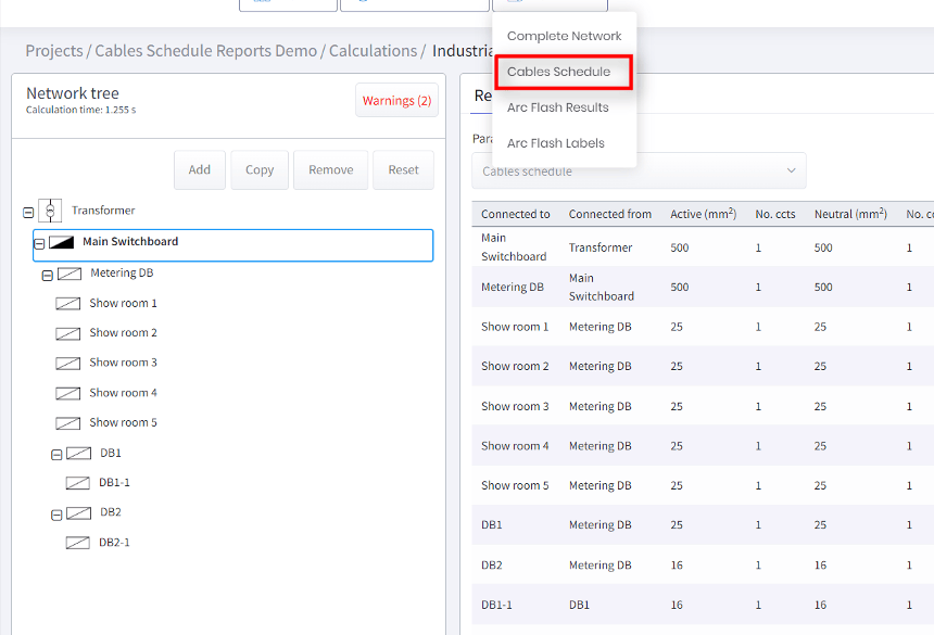
9. Generating Reports
Once your calculation is complete, generate a detailed report from the Cable Sizing menu. The report includes all inputs, correction factors, ampacity results, voltage drop results, EGC sizing, and NEC article references, ready for client delivery or engineering sign-off.
Standard Assumptions
| Parameter | Value |
|---|---|
| Indoor ambient temperature | 30 °C (86 °F) |
| Outdoor ambient temperature | 40 °C (104 °F) |
| Rooftop addition | +33 °C |
| Soil temperature | 20 °C |
| Maximum current-carrying conductors (pre-adjustment) | 3 |
| Terminal temperature compliance | Article 110.14(C) |
NEC Article References
| Calculation | Reference |
|---|---|
| Ampacity tables | Article 310 (Tables 310.16–310.21) |
| Terminal temperature rating | Article 110.14(C) |
| Insulation types | Article 310.4 |
| OCPD standard ratings | Article 240 |
| Small-conductor protection limits | Article 240.4(D) |
| EGC sizing | Article 250.122 |
| Cable tray correction factors | Article 392.80 |
| Duct bank and direct burial | Appendix B.2 |
| Rooftop exposure | Article 310.15(B)(3)(c) |
| Multiple conductor adjustment | Article 310.15(C) |
| Dwelling services | Article 310.12 |
| Resistance and reactance values | Chapter 8, Table 9 |