Downloads:
Table of Contents
Introduction
ELEK Cable HV™ Software can perform custom current rating calculations for a wide range of modern extruded power cables of varying constructions can be modelled including cables for DC and AC applications, single phase or three phases, multi-core of single core cables, sheathed and armoured cables. The built-in cable editor provides considerable flexibility in specifying the parameters for the various components of which a cable may be comprised.
To model a cable and determine its current rating requires knowledge about its physical construction. This information is obtained from cable manufacturer datasheets.
This tutorial will explain how to model several types of cables using Cable HV™ Software:
- Cable Model 1 – Single core 33 kV, XLPE insulated cable
- Cable Model 2 – Single core 5 kV DC, XLPO insulated cable for solar applications
- Cable Model 3 – Multi-core 400 kV, single-armour submarine fibre optic composite power cable
New methods to calculate the cable losses in three-core armoured cables was introduced with CIGRE Technical Brochure 908 (2023). This technical brochure improves the IEC 60287-1-1 loss factor empirical equations, which are based on early research performed on cables with small conductor cross sections and common sheath. In general, for three-core armoured cables the current rating is increased by approximately 10 %.
The model is validated by calculating the current ratings in various standard configurations and comparing with results in the manufacturer datasheet (where provided).
Cable Model 1: Single core 33 kV, XLPE insulated cable
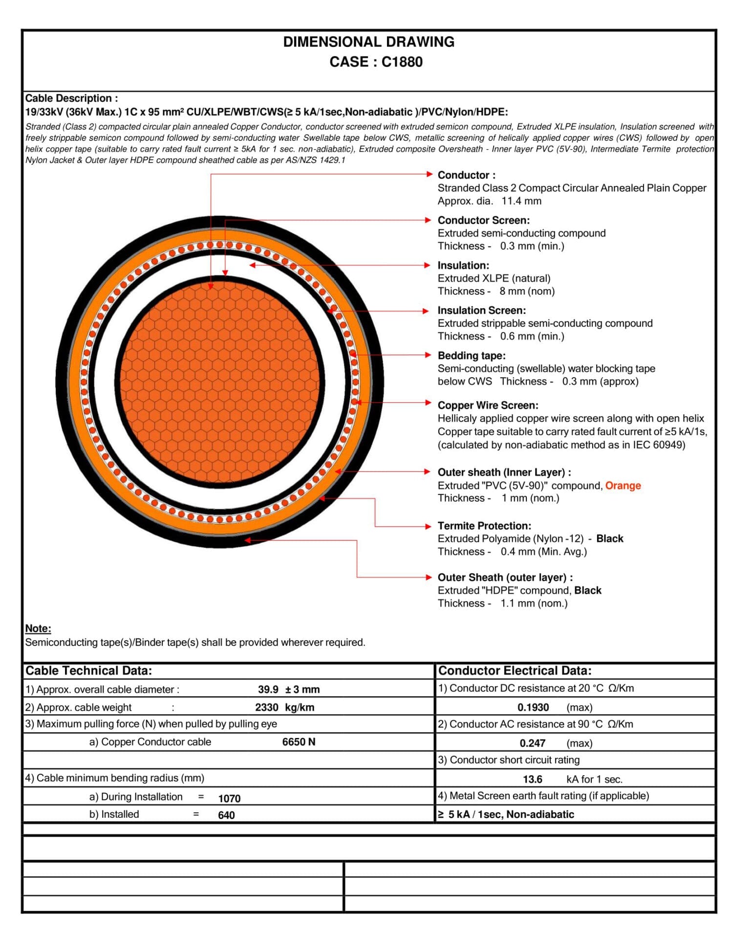
The full description of this cable is 19/33 kV, single-core, 95 mm2 Cu, XLPE insulated cable.
Cable manufacturer datasheet
Based on the parameters shown in the datasheet, the cable can be modelled in Cable HV™ Software.
Modelling the cable
Step 1 – Select the cable layers
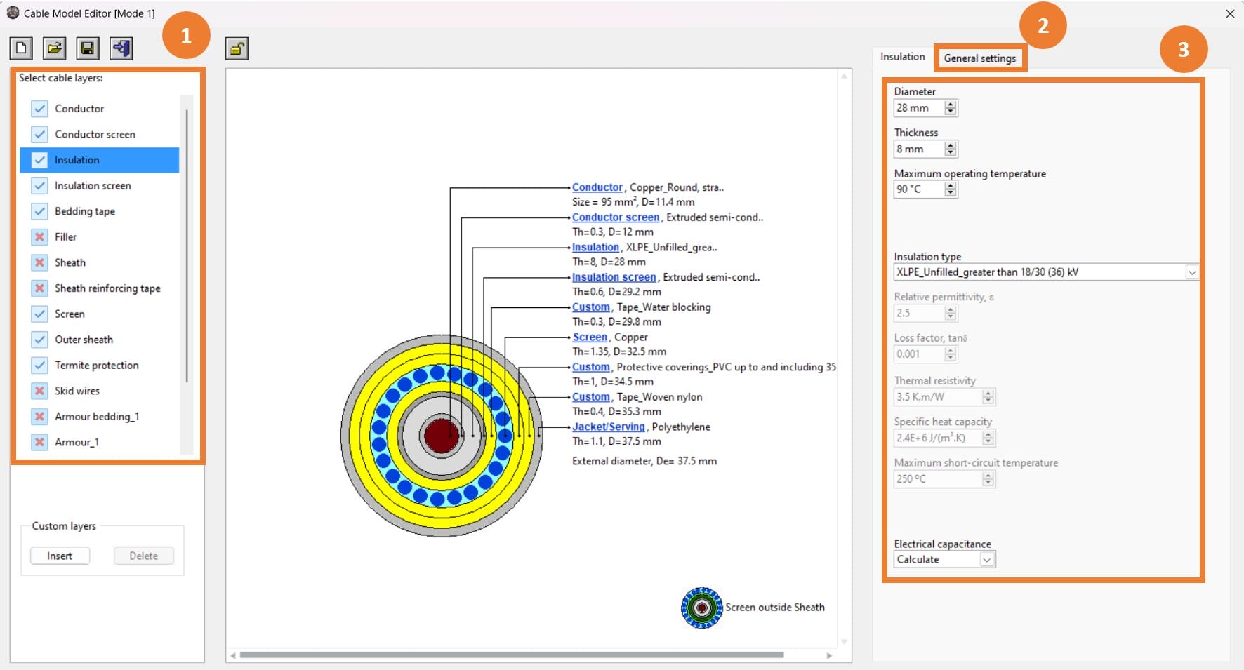
On the left-hand side of the Cable Editor window select the cable layers which are present for the Cable Model. In the case of Cable Model 1 the following cable layers are present:
1. Conductor
2.Conductor shield -For modelling the conductor screen in the datasheet.
3. Insulation
4. Insulation screen
5. Bedding tape-Custom layer added for Bedding (water-blocking) tape
6. Concentric neutral – For modeling the copper wire screen in the
7. Outer sheath – Custom layer added for outer sheath.
8. Termite protection – Custom layer added for termite protection layer.
9. Jacket/Serving
Step 2 – Input the general settings
Input general settings – Description, Cable type, Phases, Cores, Voltage and Frequency – for the Cable Model.
| Setting | Value | ||||||||||
|---|---|---|---|---|---|---|---|---|---|---|---|
| Cable type | Extruded | ||||||||||
| Cores | Single-core | ||||||||||
| Phases | Three-phase | ||||||||||
| Voltage (phase to phase) | 33 kV | ||||||||||
| Frequency | 50 Hz | ||||||||||
| Installation Settings | |||||||||||
| Calculation based on | Conductor Temperature | ||||||||||
| Maximum conductor operating temperature | Same as cable insulation | ||||||||||
| Load factor | 1 | ||||||||||
| Arrangement | Solidly bonded | ||||||||||
Step 3 – Input the layer parameters
The input parameters from the datasheet are summarized in Table 2 and these values are entered into the Cable Editor by selecting the appropriate layer from the preview.
Table 1 – Parameters of Cable Model 1
| Layer | Parameter | Value | |||||||||
|---|---|---|---|---|---|---|---|---|---|---|---|
| Conductor |
Size Class Material Conductor type Nominal diameter |
95 mm2 2 Copper, plain wires Copper_Round, stranded (Extruded/Mineral insulation) 11.4 mm |
|||||||||
| Conductor shield |
Material Thickness |
Extruded semi-conductor 0.3 mm |
|||||||||
| Insulation |
Material Thickness Maximum operating temperature |
XLPE_Unfilled_greater than 18/30 (36) kV 8 mm 90 ℃ |
|||||||||
| Insulation screen |
Material Thickness |
Extruded semi-conductor 0.6 mm |
|||||||||
| Bedding tape |
Material Thickness |
Tape_Water blocking 0.3 mm |
|||||||||
| Concentric neutral1 |
Material Construction Thickness Number of wires |
Copper Round wires 1.35 mm 48 |
|||||||||
| Outer sheath |
Material Thickness |
Protective coverings_PVC up to and including 35 kV cables 1 mm |
|||||||||
| Termite protection |
Material Thickness |
Tape_Woven nylon 0.4 mm |
|||||||||
| Jacket/Serving |
Material Thickness |
Polyethylene 1.1 mm |
|||||||||
| Overall Diameter of all cables: 37.5 mm | |||||||||||
Notes:
- According to the datasheet, lay length shall not exceed 10 times the pitch circle diameter of the wire screen. Here, pitch length of Screen is 31.15 mm. Therefore, Lay Length = 312 mm.
The thickness of the Concentric neutral is not given in the datasheet. We assumed a thickness of 1.35 mm - Validation of the current rating
Cable Model 1 was validated by comparing the calculated current ratings from Cable HV™ Software with those for standard configurations from the manufacturer datasheet.
According to the manufacturer datasheet the installation conditions are:
- Ambient air temperature: 40 °C
- Ambient soil temperature: 25 °C
- Soil thermal resistivity: 2 K.m/W
- Depth of lying: 0.8
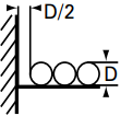
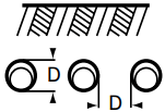
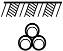
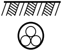
The Cable Model 1 current rating comparison is shown in Table 3
Table 3 – Validation of Cable Model 1
| Installation | Current rating (A) | Variation (%) | ||
| Datasheet | Cable HV™ | |||
| In Air |
|
333 | 336.9 | 1.16 |

|
315 | 314.02 | 0.31 | |

|
332 | 331.31 | 0.21 | |
| Buried Direct |

|
297 | 301.39 | 1.46 |

|
292 | 301.11 | 3.03 | |

|
297 | 296.97 | 0.01 | |
| Buried in Ducts |

|
265 | 263.14 | 0.70 |
|
258 | 268.72 | 3.99 | |
|
267 | 269.39 | 0.89 | |
|
258 | 251.72 | 2.43 | |
As the current ratings between Cable HV™ and the manufacturer datasheet are close, it can be concluded that the cable has been modelled correctly.
Note:
- From the datasheet, D is the diameter of the cable and the distance between two cables is Since separation is calculated from core to core for cables, the separation here will be (0.5D + 0.5D) + D = 2D. In the calculator, we put separation as 2.
- Duct diameter is not provided in the datasheet.
For cables combined in a single duct, duct outside diameter = 100 mm and duct inside diameter = 90 mm is assumed.
For cables in separate ducts, duct outside diameter = 65 mm and duct inside diameter = 55 mm is assumed.
For the duct settings, PVC is used as duct material and for fill type, Air is selected.
Cable Model 2: Single core 1.5 kV DC, XLPO insulated cable
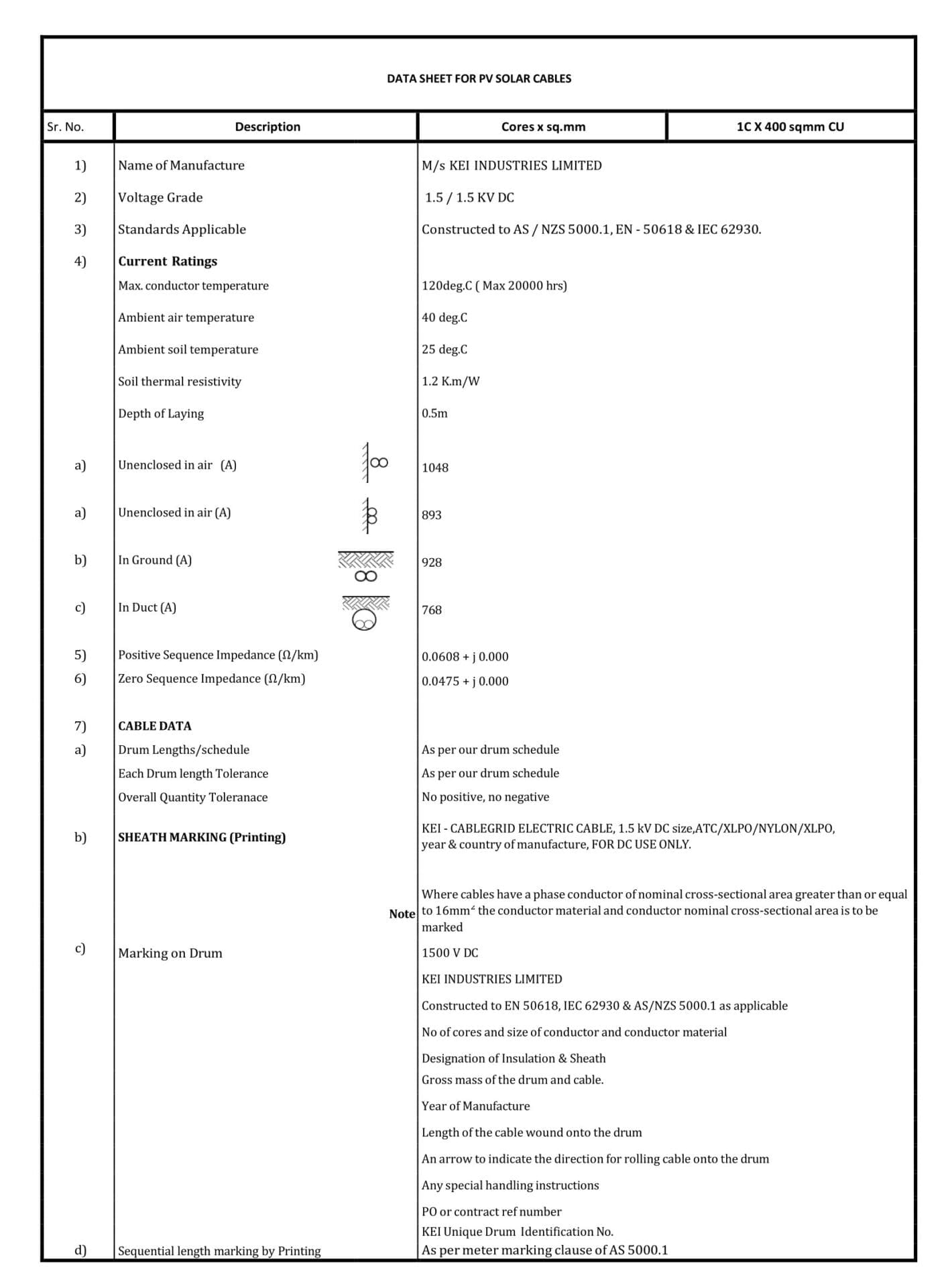
The full description of this cable is 1.5 kV DC, single-core, 400 mm2 Cu, XLPO insulated cable.
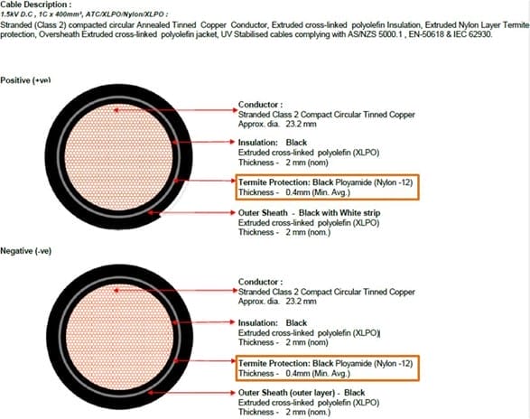
Cable manufacturer datasheet
Based on the parameters shown in the datasheet, the cable can be modelled in Cable HV™.
Modelling the cable
Step 1 – Select the cable layers
On the left-hand side of the Cable Editor window select the cable layers which are present for the Cable Model. In the case of Cable Model 2 the following cable layers are present:
- Conductor
- Insulation
- Termite Protection – Custom layer added for termite protection layer
- Jacket/Serving
Step 2 – Input the general settings
Input general settings – Cable type, Phases, Cores, Voltage – for the Cable Model.
Table 4 – General Settings of Cable Model 2
| Setting | Value | ||||||||||
|---|---|---|---|---|---|---|---|---|---|---|---|
| Cable type | Extruded | ||||||||||
| Cores | Single-core | ||||||||||
| Phases | DC | ||||||||||
| Voltage (phase to phase) | 1.5 kV | ||||||||||
| Installation Settings | |||||||||||
| Calculation based on | Conductor Temperature | ||||||||||
| Maximum conductor operating temperature | Same as cable insulation | ||||||||||
| Load factor | 1 | ||||||||||
| Arrangement | Solidly bonded | ||||||||||
Step 3 – Input the layer parameters
The input parameters from the datasheet are summarized in Table 5 and these values are entered into the Cable Editor by selecting the appropriate layer from the preview.
Table 5 – Parameters of Cable Model 2
| Layer | Parameter | Value | |||||||||
|---|---|---|---|---|---|---|---|---|---|---|---|
| Conductor |
Size Class Material Conductor type Nominal diameter |
400 mm2 2 Copper, metal-coated wires Copper_Round, stranded (Fluid/paper/PPL insulation) 23.2 mm |
|||||||||
| Insulation |
Material Thickness Maximum operating temperature |
XLPE_Unfilled_greater than 18/30 (36) kV 2 mm 120 deg.C. |
|||||||||
| Termite Protection |
Material Thickness |
Tape_Woven nylon 0.4 mm |
|||||||||
| Jacket/Serving |
Material Thickness |
Polyethylene 2 mm |
|||||||||
| Overall diameter of the cable: 32 mm | |||||||||||
Figure 4 shows the combined layer of the Cable Model in Cable HV™
Validation of the current rating
Cable Model 2 was validated by comparing the calculated current ratings from Cable HV™ Software with those for standard configurations from the manufacturer datasheet.
According to the manufacturer datasheet the installation conditions are:
- Ambient air temperature: 40 °C
- Ambient soil temperature: 25 °C
- Soil thermal resistivity: 2 K.m/W
- Depth of laying: 5 m
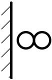
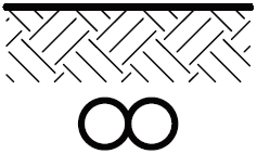
The current rating comparison is shown in Table 6.
Table 6 – Validation of Cable Model 2
| Installation | Current rating (A) | Variation (%) | ||
| Datasheet | Cable HV™ | |||
| In Air |
|
1048 | 1062.83 | 1.40 |
| Buried Direct |
|
928 | 777.13 | 16.26 |
| Buried in Ducts |

|
768 | 779.64 | 1.49 |
As the current ratings are close, it can be concluded that the assumption of modelling termite protection is reasonable.
Note:
- Duct diameter is not provided in the datasheet. For cables in separate ducts, duct outside diameter = 75 mm and duct inside diameter = 72 mm is assumed.
For the duct settings, PVC is used as duct material and for fill type, Air is selected.
Cable Model 3: Multi-core 400 kV single-armour submarine fibre optic composite power cable
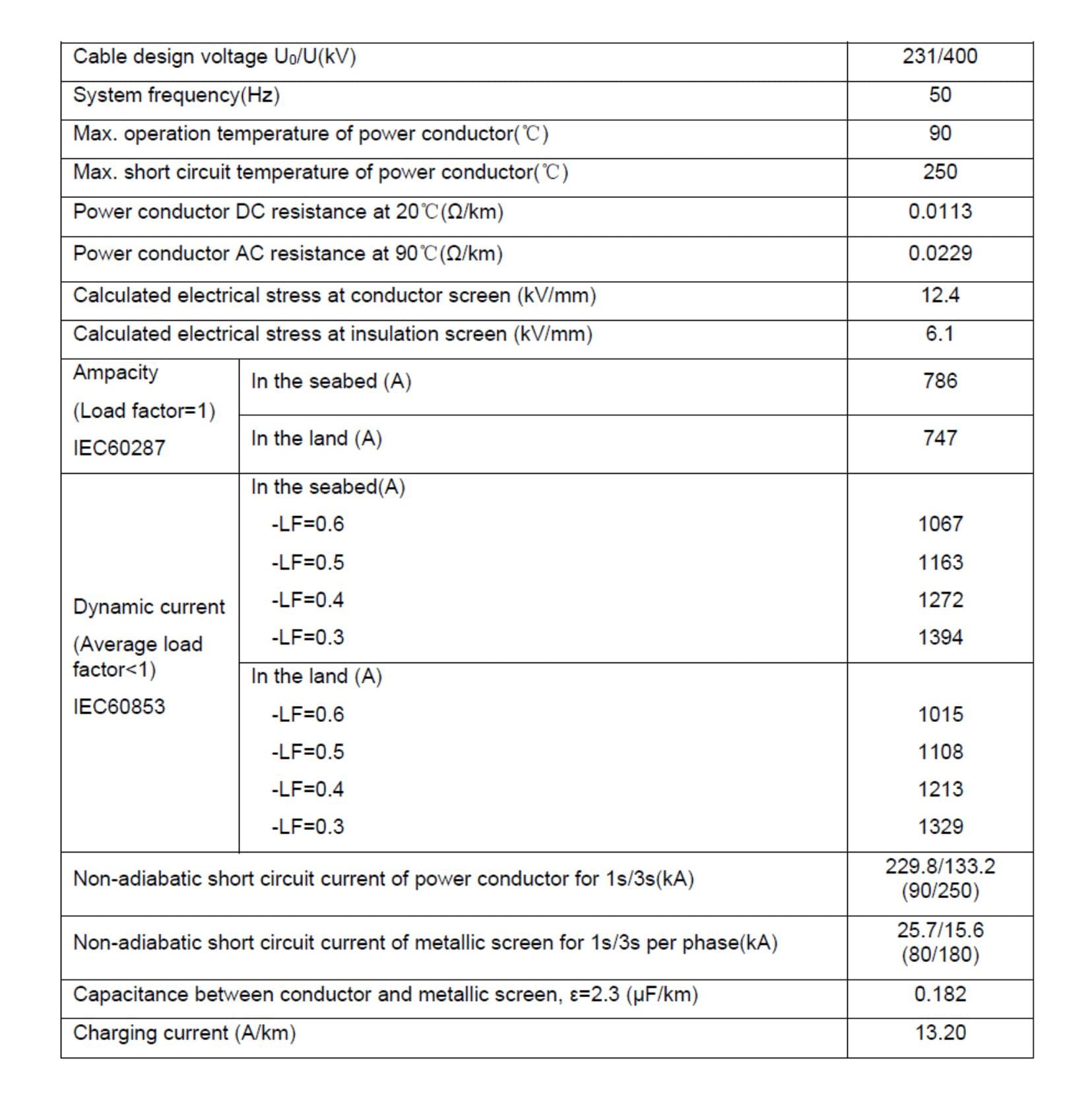
The full description of this cable is 400kV, 3 core, 1600 mm2 single-armour submarine fibre optic composite power cable.
Cable manufacturer datasheet
Based on the parameters shown in the datasheet, the cable can be modelled in Cable HV™.
Modelling the cable
Step 1 – Select the cable layers
On the left-hand side of the Cable Editor window select the cable layers which are present for the Cable Model. In the case of Cable Model 3 the following cable layers are present:
- Conductor
- Conductor shield – For modelling the conductor screen in the
- Insulation
- Insulation screen
- Semi-conducting tape – Custom layer for semi conducting tape.
- Sheath
- Outer sheath – Custom layer for outer sheath.
- Filler
- Binding tape – Custom layer for binding tape.
- Bedding – Custom layer for bedding.
- Armour
- Jacket/Serving
Note:
FOC unit is ignored for this cable model.
Step 2 – Input the general settings
Input general settings – Description, Cable type, Phases, Cores, Voltage and Frequency – for the Cable Model.
Table 7 – General Settings of Cable Model 3
| Setting | Value | ||||||||||
|---|---|---|---|---|---|---|---|---|---|---|---|
| Cable type | Submarine | ||||||||||
| Cores | Three-core | ||||||||||
| Phases | Three-phase | ||||||||||
| Voltage (phase to phase) | 400 kV | ||||||||||
| Frequency | 50 Hz | ||||||||||
| Lay length | Calculate | ||||||||||
| Core lay length | 3500 mm | ||||||||||
| Installation Settings | |||||||||||
| Calculation based on | Conductor Temperature | ||||||||||
| Maximum conductor operating temperature | Same as cable insulation | ||||||||||
| Load factor | Varied according to experiment | ||||||||||
| Arrangement | Solidly bonded | ||||||||||
Step 3 – Input the layer parameters
The input parameters from the datasheet are summarized in Table 8 and these values are entered into the Cable Editor by selecting the appropriate layer from the preview.
Table 8 – Parameters of Cable Model 3
| Cable Layer | Parameter | Value | |||||||||
|---|---|---|---|---|---|---|---|---|---|---|---|
| Conductor1 |
Size Class Material Conductor Type Nominal diameter |
1600 mm2 Class 2 Copper, plain wires Copper_Round, stranded (Fluid/paper/insulation) 47.6 mm |
|||||||||
| Conductor screen |
Diameter Material |
52.7 mm Extruded semi-conductors |
|||||||||
| Insulation |
Material Diameter Maximum operating temperature |
XLPE_Unfilled_greater than 18/30 (36) kV 106.7 mm 90 deg.C |
|||||||||
| Insulation screen |
Material Diameter |
Extruded semi-conductor 109.1 mm |
|||||||||
| Semi-conducting tape |
Material Diameter |
Tape_Water blocking 113.1 mm |
|||||||||
| Sheath |
Material Diameter |
Lead 119.1 mm |
|||||||||
| Outer sheath |
Material Diameter |
Insulation_PE (HD and LD) 125.1 mm |
|||||||||
| Filler |
Material Diameter |
Unknown – TR same as 269.553 mm |
|||||||||
| Binding tape2 |
Material Diameter |
Tape_Water blocking 269.555 mm |
|||||||||
| Bedding3 |
Material Diameter |
Polypropylene yarn 271.9 mm |
|||||||||
| Armour_14 |
Material Construction Diameter No. of wires |
Steel Wires touching 283.9 mm 137 |
|||||||||
| Jacket/Serving |
Material Diameter |
Polypropylene yarn 295.9 mm |
|||||||||
| Overall diameter of the cable: 295.9 mm | |||||||||||
Note:
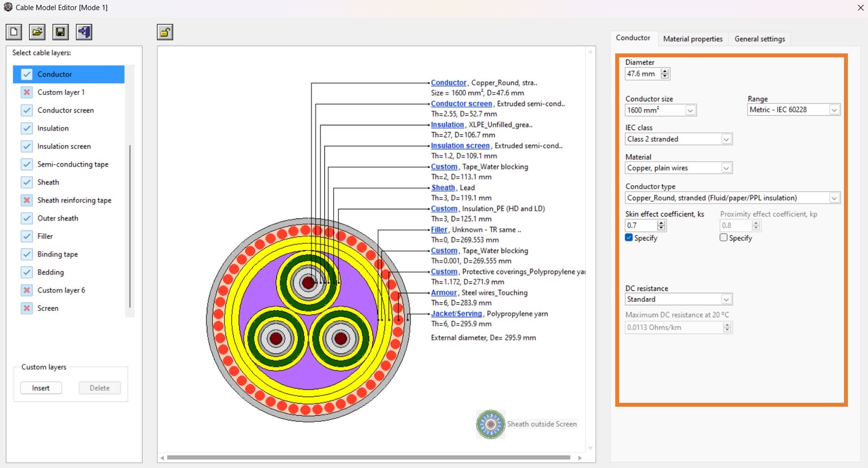
- For the conductor, skin effect coefficient (ks) of 7 is specified.
- Since FOC unit is ignored, the thickness of the binding is set to minimum at 0.001 mm.
- The thickness of the bedding is assumed to be 1.172 mm to match the diameter with the datasheet.
- Armour length of lay is not specified, hence length of lay is specified to 2740 mm and Lay direction is Contralay.
Validation of the current rating
Cable Model 3 was validated by comparing the calculated current ratings from Cable HV™ Software with those for standard configurations from the manufacturer datasheet.
According to the manufacturer datasheet the installation conditions are:
- Ambient soil temperature: 26 °C
- Soil thermal resistivity: 8 K.m/W
- Depth of laying: 3 m
The current rating comparison is shown in Table 9.
Table 9 – Validation of Cable Model 3
| Installation | Current rating (A) | Variation- IEC (%) | Variation- TB 908 (%) | |||
| Condition | Load Factor | Datasheet | Cable HV-IEC | Cable HV-TB 908 | ||
| Buried | 0.3 | 1394 | 1394.25 | 1444.59 | 0.01 | 3.50 |
| 0.4 | 1272 | 1263.37 | 1331.19 | 0.68 | 4.45 | |
| 0.5 | 1163 | 1147.94 | 1226.83 | 1.30 | 5.20 | |
| 0.6 | 1067 | 1047.48 | 1132.66 | 1.85 | 5.80 | |
As the current ratings with the IEC method are close, it can be concluded that the assumption of modelling water blocking tape and outermost layer is reasonable.
Note:
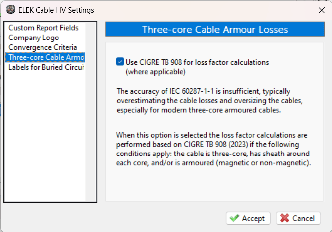
By default, the calculator performs the calculations by TB 908 method. In order to change the calculation to IEC method, click on the tools dropdown and go to settings. From Cable HV Settings, go to the “Three-core Cable Armour Losses” tab, uncheck the TB 908 check box. See figure 7 for reference.

