Table of Contents
Ensuring Accurate FEM-based Cable Rating Calculations
The finite element method (FEM) is increasingly used for cable ampacity calculations in complex installations where IEC 60287 analytical methods are insufficient. Validation against established benchmarks is essential to ensure accuracy and reliability of the finite element analysis.
Under the guidance of industry experts, CIGRE Technical Brochure 963 (WG B1.87) [1] was developed to establish benchmark case studies for FEM-based cable rating calculations. TB 963 provides formal guidance and a comprehensive set of recommendations towards best practices.
While FEM is widely used for cable ampacity calculations in complex installations, its results are highly dependent on modelling assumptions. Without validation against recognised benchmarks, FEM outputs cannot be relied upon for engineering decisions. CIGRE TB 963 provides one of the few internationally accepted references for this purpose.
This article demonstrates the FEM validation process using ELEK Cable HV Software™ [4] as an example. Its IEC 60287 calculations have already been validated against CIGRE Technical Brochure 880 with excellent agreement (see the IEC 60287 validation article), and here we complement that work by benchmarking the FEM-based cable rating calculations against CIGRE Technical Brochure 963 to confirm accuracy for practising cable engineers.
Understanding FEM for Cable Ampacity Calculations
While the IEC 60287 [3] standard provides well-established analytical equations for calculating cable current ratings, specific complex installations are difficult to model, and some assumptions lead to inaccurate results. Numerical methods aim to achieve accurate results. Heat dissipation around the cable is essential for calculating cable ampacity and is directly affected by the thermal resistivity (TR) of each component, including the duct filler, backfill material, and native soil. The FEM offers a powerful approach for modelling thermal behaviour in scenarios where analytical methods reach their limitations, such as cables installed in ducts with multiple soil layers and temperature-dependent thermal properties.
FEM is a numerical technique that solves physical equations. For cable ampacity calculations, FEM solves heat transfer equations by dividing the continuous temperature field around cables into discrete parts. Each component (cable layers, duct, backfill, soil) is meshed separately to accurately represent different thermal properties. The calculation process consists of five key steps:

The key concepts introduced in the workflow above are:
- Elements: Small pieces that make up the computational domain (polygons in 2D or polyhedra in 3D). Within each element, the heat transfer equation is linearised.
- Nodes: The corners of elements where the solution is calculated. Temperatures at other locations are interpolated.
- Mesh: The complete collection of all elements and nodes that covers the entire calculation area.
- Boundary conditions: FEM solves partial differential equations (like the heat conduction equation). However, these equations need boundary conditions to get a unique solution. Boundary conditions define the physical behaviour of the model edges.

Introduction to ELEK Cable HV™ Software
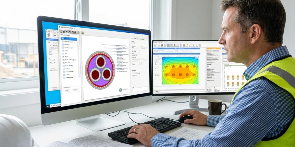
To meet industry needs for both analytical and numerical cable rating calculations, we developed ELEK Cable HV™, a specialised software tool that accurately calculates high-voltage cable current ratings. The software performs calculations in accordance with the internationally recognised IEC Standard 60287 [3] and incorporates the finite element method (FEM) for scenarios beyond the scope of standards.
ELEK Cable HV™ is a powerful, easy-to-use software that is widely adopted for cable design engineering. Visit the technical product page to read about the full range of features and to access a free trial of the software.


Validation Process for FEM-Based Cable Ampacity Calculations
The validation process involves the following steps:
- Review the benchmark: Study the methodologies, FEM modelling approaches, and case studies in CIGRE TB 963, which serve as the reference for validation.
- Select a case study: Choose an appropriate case study from TB 963. This article uses Case Study 1, which involves cables in ducts with multi-layer soil.
- Configure the FEM model: Set up the cable model, installation geometry, material properties, and boundary conditions to match the case study specifications.
- Compare results: Evaluate performance by calculating the relative error against CIGRE FEM results. Compare current ratings and soil temperature distributions for each variation.
Case Study 1 from CIGRE TB 963: Six Modelling Variations
The validation case studies are based on “Case Study 1” from CIGRE Technical Brochure 963, which provides a comprehensive benchmark for FEM current rating calculations. The case study comprises a base model (Variation 0) with standard installation conditions, along with five additional variations that progressively introduce more complex modelling scenarios. Running multiple variations is essential for FEM validation, as it confirms the model performs accurately across different installation conditions, not just a single scenario.
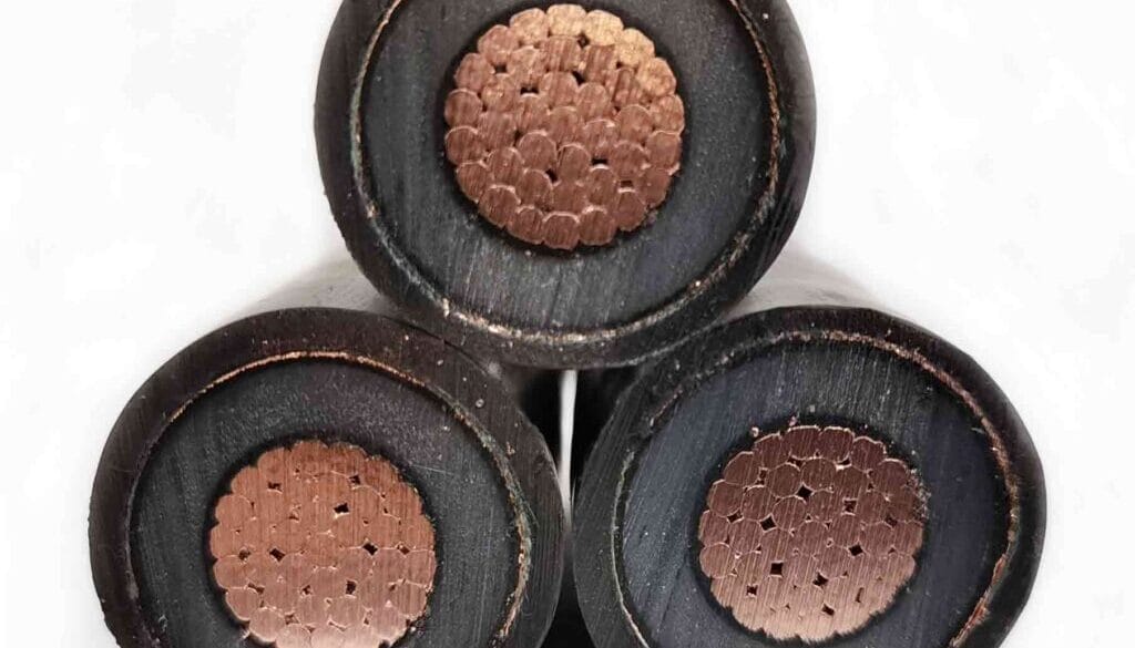
The cable model is based on Case 0 from CIGRE Technical Brochure 880 [2]: a 132 kV land cable with a stranded copper conductor of 630 mm² cross section and an aluminium-laminated foil sheath of 170 mm² cross section.
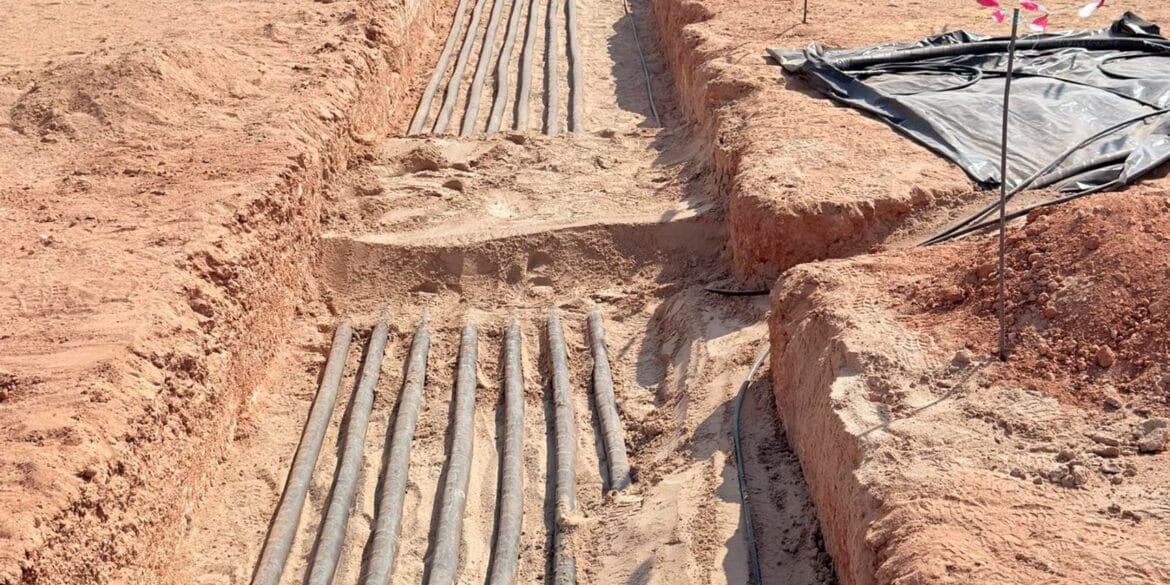
Cable Installation Configuration

Comparison of FEM-based Ampacity Results
Variation 0 (Base model) - IEC Equivalent Thermal Resistance for Duct Air
This variation uses solid bonding in a flat formation. The thermal modelling of air within the ducts follows the IEC 60287 standard approach, which simplifies the complex convection and radiation heat transfer mechanisms into an equivalent thermal resistance. Additionally, the cable is assumed to be positioned at the centre of the duct.
With solid bonding, asymmetric cable positioning causes uneven sheath-circulating currents. The lagging phase experiences higher sheath losses than the centre phase due to heat dissipation, making it the limiting cable for the circuit rating. The soil temperature distribution by FEM should reflect this asymmetric thermal behaviour.

Variation 1 - Modelling Heat Transfer for Duct Air
This variation uses the same configuration as variation 0 but replaces the IEC 60287 simplified equivalent thermal resistance method with explicit FEM modelling of laminar convection and surface-to-surface radiation within the ducts. This approach enables realistic cable positioning at the duct bottom rather than at the assumed centre.
This variation demonstrates the FEM’s capability to model actual installation conditions in which cables naturally rest on the inner surface of the duct due to gravity.

Variation 2 - Sheath Single Point Bonding
This variation uses the exact same model as variation 0, with only the bonding configuration changed from solid to single point. With this configuration, circulating currents are eliminated, and only eddy currents contribute to sheath losses, so current ratings will be higher.
Figure 8 shows a significant increase in cable ampacity under single bonding, demonstrating the FEM model’s ability to correctly implement single-bonding boundary conditions.

Variation 3 - Bentonite as Duct Filling Material
This variation uses the same model as the base case, with only the duct filling material changed from air to bentonite. Bentonite has a low TR (0.4 K·m/W), which improves thermal dissipation compared to air-filled ducts.
In the base model, the air inside the ducts is modelled according to IEC 60287, which assumes the cable is centred in the duct. However, with bentonite as a solid filling material, there is no air convection inside. Thus, it is no longer necessary to refer to the IEC standard, and centred cable is no longer an assumption.

Variation 6 - Temperature-Dependent Soil Thermal Resistivity (Soil Dry-Out)
This variation is based on Variation 0, with the native soil TR modelled as temperature-dependent to simulate soil dry-out conditions. The backfill material is assumed to resist drying and remain thermally stable. The native soil TR is set to 1 K·m/W under normal conditions. When the soil temperature reaches the critical threshold of 45 °C, the TR increases to 2.5 K·m/W.
This variation tests the FEM model’s capability to handle the non-linear, temperature-dependent material properties.
Soil Thermal Resistivity Profile


This variation modifies the Case 0 cable model by adding a copper wire-screen layer beneath the sheath and two swelling tapes. All installation conditions remain unchanged from the base model. It should be noted that the thermal resistivity of the swelling tapes is not specified in the CIGRE TB 963 document. A value of 12 K·m/W has been assumed, which represents a significant source of uncertainty and may contribute to discrepancies between CIGRE and ELEK Cable HV results.
This variation tests the FEM model’s ability to handle additional cable layers with different thermal properties, a common feature of practical cable constructions.
Variation 7 -Additional Cable Layers (Copper Wire Screen and Swelling Tapes)

Conclusions - ELEK Cable HV™ Successfully Validated
FEM is a numerical method used to model complex cable installations that cannot be adequately addressed by standard analytical approaches. This article reviewed the basic principles of FEM and demonstrated the validation process using CIGRE TB 963 as a benchmark. The above case study shows agreement between the ELEK Cable HV™ FEM results and the results published in CIGRE TB 963. The following conclusions can be drawn.
- Validating FEM-based cable ampacity results against established benchmarks such as CIGRE TB 963 is essential before applying them to real engineering projects.
- Testing multiple modelling variations is necessary to confirm FEM accuracy across different installation conditions.
- FEM is recommended when installations involve conditions beyond the limitations of IEC 60287.
- Minor deviations from benchmark results are expected due to differences in mesh settings, solver parameters, and undefined material properties.
- ELEK Cable HV™ FEM calculations show close agreement with CIGRE TB 963, confirming the validity of the software’s modelling approach.
References
[1] CIGRE B1 Insulated Cables Technical Brochure. “Finite Element Analysis for Cable Rating Calculations.” Reference 963. May 2025.
[2] CIGRE B1 Insulated Cables Technical Brochure. “Guidelines for the Rating Calculations of Insulated Cables.” Reference 880. September 2021.
[3] IEC 60287:2023 SER Series. Electric cables – ALL PARTS.
[4] ELEK Cable High Voltage Software Version 9.0.
Frequently Asked Questions
General Concepts: IEC vs. FEM
Q: What is the main difference between IEC 60287 and FEM for cable ratings? A: IEC 60287 uses analytical equations to calculate ratings, which are generally accurate for standard installations but rely on simplified assumptions. FEM (Finite Element Method) is a numerical approach that divides the model into a mesh of thousands of small triangles to calculate the temperature at specific nodes. FEM allows for modelling complex geometries and heat transfer effects that the IEC standard cannot handle, such as non-isothermal ground surfaces and convection.
Q: Why are IEC 60287 calculations sometimes considered “optimistic” or inaccurate? A: The IEC standard assumes the ground surface is isothermal (constant temperature) and ignores heat transfer (convection) between the ground and the air. Research suggests this assumption leads to over-rating (optimistic ratings) for cables buried shallower than 1 meter, including those in surface troughs. Furthermore, IEC uses the superposition principle for mutual heating, which is less accurate than FEM for cables that are touching or in close proximity.
Q: When should I use FEM instead of the IEC standard? A: You should use FEM for complex scenarios where IEC equations are insufficient. This includes installations with:
- Heterogeneous soils (multiple zones of different thermal resistivity).
- Cables inside ducts within larger pipes (e.g., HDD or multiple casings).
- Large groups of cables or complex touching arrangements.
- Situations requiring high accuracy regarding soil drying or air convection. For simple, well-defined cases, the IEC method is often sufficient and faster.
Technical Modelling & Environmental Factors
Q: How does FEM handle soil drying differently than IEC? A: The IEC method for soil drying is limited; it typically applies only to single circuits, unity load factors, and direct burial. FEM uses a two-zone approach where a “critical temperature” (typically 40°C to 50°C) is defined. If the soil temperature exceeds this limit, the software automatically applies a dry thermal resistivity to that zone. This dynamic process allows soil drying to be calculated for multiple buried circuits and complex backfills.
Q: How is air inside ducts modelled? A: Modelling air in ducts is complex because hot air rises and circulates (convection). In FEM, this convection is modelled iteratively to account for the heat transfer loop where air heats up around the cable and cools against the duct wall. This provides a more accurate rating than static air models.
Q: Can I model multiple soil layers or backfills? A: Yes. Unlike IEC, which generally limits you to a single backfill with specific dimension ratios, FEM allows you to model an unlimited number of zones with different thermal resistivities. This is essential for modern installations, such as renewable energy trench designs, where cables may be installed in specific bedding surrounded by native soil and other materials.
Software & Validation
Q: How is the software validated? A: The software discussed (ELEK Cable HV) is validated against CIGRE Technical Brochure 880 for IEC calculations and CIGRE Technical Brochure 963 for FEM calculations. The developers have verified that their results match the case studies in these documents to within a very small percentage.
Q: Does FEM require a lot of manual setup (meshing)? A: In general, FEM software, setting up the mesh and boundary conditions, can take hours or days. However, ELEK Cable HV automates the mesh generation, boundary conditions, and material assignments, making it almost as fast to set up as a standard IEC calculation.
Q: How does the “Hybrid” calculation method work? A: ELEK Cable HV software utilises a combined algorithm. It uses standard IEC 60287 equations to calculate internal cable parameters (such as dielectric losses and the internal thermal resistances T1, T2, T3), but uses FEM to calculate the external thermal resistance (T4) of the environment. This T4 value is then fed back into the IEC current rating equation to provide the final result, combining standard compliance with FEM accuracy.
Q: What is the best practice for entering cable data from a manufacturer’s datasheet? A: When modelling a cable, you should prioritise the diameter over the thickness specified in the datasheet. If the calculated thickness based on the diameter differs from the datasheet thickness, the diameter takes precedence to ensure accurate geometric modelling for the FEM mesh.