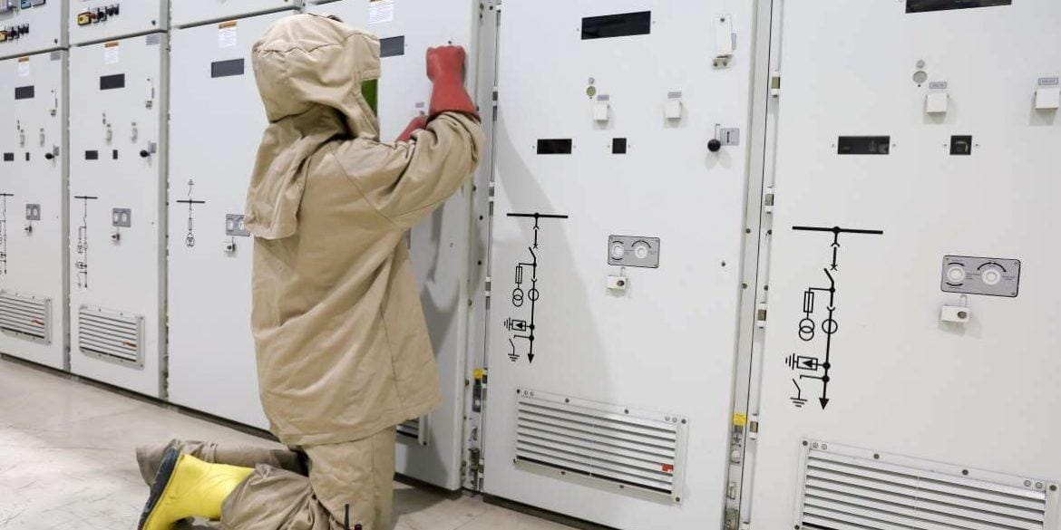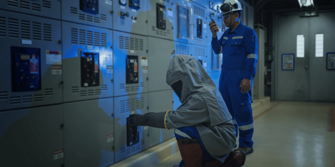
What is arc flash?
Arc flash is defined as an electric arc event where current flows through the air between phase conductors and thermal energy is dissipated as radiant, convective, and conductive heat. An arc flash is an explosive event causing dangerous conditions resulting in serious injury or even death to workers or nearby persons, ignition of flammable materials and damage to equipment.
Electrical equipment operating at or above 50 V AC or 120 V DC (ripple free) which will not put into a deenergised state during work must be evaluated for arc flash and shock protection.
This evaluation will determine the incident energy, arc flash boundaries and safety labels will inform the electrical workers of what PPE must be worn.
What causes an arc flash?
Arc flash explosions are not only caused by workers dropping tools or by accidental touching but can also be caused by several factors which are less obvious such as build-up of dust or condensation, material failure, corrosion, or a faulty installation.
The three most dangerous activities of workers which carry the highest risk of arc flash are [3]:
- Restoration after a fault or operation of equipment with possible defect.
- Racking (panel open) – racking circuit breaker, panel open with racking handle.
- Commissioning – switching electrical equipment on for the first time.
Contributing human factors from workers includes that they have not undertaken a risk assessment, or their risk assessment was inadequate, they failed to isolate or test the isolation, lack of experience or competency.
What happens during arc flash?
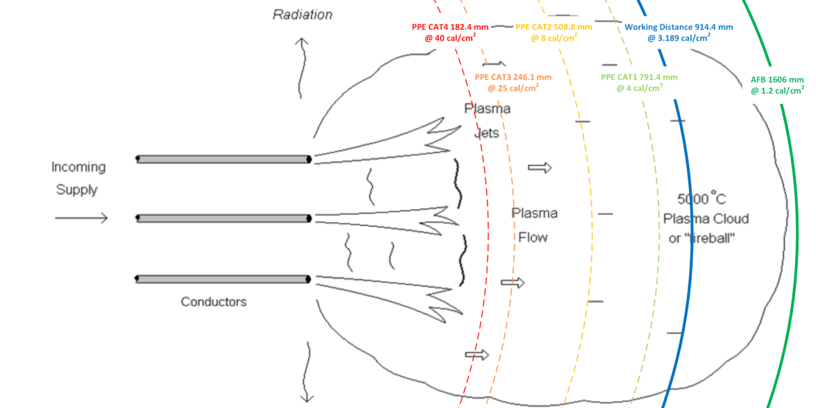
The arc flash energy is fed by the fault current flowing through an electrical arc plasma (super-heated ionised gas at more than 5000˚C) which is ejected by the arc and stops only once the arcing current is interrupted by the electrical protection. There are several effects caused by an arc flash explosion including intense light, pressure waves, sound waves, hot air and vapour however the arc plasma which is ejected is the major hazard to an individual.
There are three main factors which determine the severity of an arc flash injury:
- Proximity of the worker to the arc flash.
- Magnitude of the arcing current and the resultant temperatures.
- Time of exposure i.e., how long it takes to clear the arc fault.
It is imperative that for workers required to undertake work on or nearby to electrical equipment, all reasonably practicable measures be taken to protect them from the harmful effects of electric arc flash hazards through hazard elimination and risk reduction.
Consequences of arc flash
Due to the violent nature of an arc flash the consequences to workers who are exposed and who are injured can be devastating or even result in death.
A technical study has shown that it only takes skin tissue to reach a temperature of 96 degrees Celsius for 0.1 seconds (5/6 cycles of 50/60 Hz current) to cause incurable burns [1].
When an arc flash occurs the extremely high temperatures can cause fatal burns at up to about 1.5 m and major burns at up to about 3 m distance from the arc [1].
Protecting workers from arc flash hazards
The best way to protect workers from arc flash is to work on deenergised electrical equipment.
If this is not feasible and the work must be performed on energised equipment, then there must be safety-related work practices in place. These could include energised electrical work permits, personal protective equipment, insulated tools, written safety programs and job briefings.
Standard working distances
IEEE Std. 1584-2018 provides working distances for high voltage (> 1 kV) switchgear = 914.4 mm (36 in), low voltage switchgear = 609.6 mm (24 in), LV MCC and cable boxes = 457.2 mm (18 in).
Typical working distances from Standards and Guides are listed below.
Arc flash study procedure
The latest IEEE Std 1584-2018 provides an arc flash study procedure which we have consolidated into 8 steps. This Standard provides empirical equations which are derived (extrapolated) from models based on statistical analysis of test measurements involving three-phase tests at 600 V with fault currents from 16-50 kA [2].
The main outcomes of the arc flash hazard study calculation are the arc flash boundary and the arc flash incident energy at defined working distances from the arcing source for selected locations in the electrical system. The results of the study will document the incident energy analysis and may be used by workers as part of an overall electrical safety risk assessment.
Note IEEE Std 1584 does not provide recommendations for PPE to mitigate arc flash hazards.
The main steps for performing arc flash study are as follows:
Step 1 –Collect system, protective device, and equipment data
- System data for short-circuit calculations, such as nominal voltage, impedance, X/R ratio, etc.
- Protective device data for determining the arc duration, such as rating, TCC, device settings, etc.
- Equipment data for incident energy and arc flash boundary. The data includes:
- Working distance – The distance between the potential arc source and the face and chest of the worker performing the task.
- Electrode configuration – The orientation and arrangement of the electrodes.
- Conductor/electrode material.
- Enclosure dimension – The height, width and depth of equipment enclosure.
- Incident energy level for determining custom arc flash boundarystudy
Typical equipment data from IEEE Std. 1584-2018 [ref. 4] listed below.
Step 2: Determine the modes/arrangements of operation
Determine the available short-circuit current for all modes of operation that provides both the maximum and minimum available short-circuit current. The short-circuit current in ‘worst condition’ is supposed to be considered for further arcing current calculations. There are several examples of mode of operation from IEEE1584-2018:
- One or more utility feeders in service
- Utility interface substation secondary bus tie circuit breaker open or closed
- Unit substation with one or two primary feeders
- Unit substation with two transformers with secondary tie opened or closed
- MCC with one or two feeders, one or both energized
- Generators running in parallel with the utility supply or in standby
- Utility system normal switching configured for maximum possible fault megavolt amperes
- Utility system normal switching configured for minimum possible fault megavolt amperes
- Separately derived sources (generators) – maximum capacity on line
- Separately derived sources (generators) – minimum number on line
- Shutdown or start-up situation with all motors in an off condition – reduced fault contribution
Step 3: Determine the bolted fault currents
Calculate the short-circuit current. The calculation should take into account the system data and modes of operation.
The three phase and single-phase short-circuit currents need to be considered. The single-phase short-circuit current is used to conduct the single-phase arc flash calculation. However, in most cases three phase short circuit currents typically give the greatest possible short circuit energy and can be considered as the worst-case. Arcing faults in devices or air that begin as line-to-ground faults, can also very rapidly step up into 3-phase faults as the air ionizes across phases. This advancement happens within a few cycles.
Step 4: Calculate the arcing current
Arcing current is usually less than bolted fault currents however the arcing current is close to bolted fault current for HV. Despite the maximum short-circuit is usually considered as worst case, the less arcing current leads to often significantly longer fault clearing times which can results in higher incident energy. Therefore, the maximum and minimum short-circuit are both necessary to be considered.
The total arcing current at the point of concern and the portion of that current passing through the upstream protective device(s) must be determined. The portion of the arcing current flowing through
the overcurrent protective device determines the arc duration.
In the case of locations being energized by multiple feeders, it is necessary to determine the portion of the total arc current passing through each protective device to determine the clearing time for each device.
Step 5: Calculate the arc duration
The arc duration is defined as the time it takes the upstream energizing source(s) of arcing current to stop providing current or energy to the arc fault, which is most commonly dependent on the operating time of a time-overcurrent protective device.
For overcurrent protective devices in series, or at locations where more than one type of protective device could clear the arcing fault (e.g., time-overcurrent relay or differential relay), the operating times must be compared to determine which will operate first.
Considering how long a person is likely to remain in the location of the arc flash, it is likely that a person exposed to an arc flash will move away quickly if it is physically possible. Two seconds usually is a reasonable assumption for the maximum arc duration to determine the incident energy.
Step 6: Calculate the incident energy
Incident energy – The amount of thermal energy impressed on a surface, a certain distance from the source, generated during an electric arc event.
The incident energy is calculated at the working distance. Incident energy increases as the distance from the potential arc source decreases, and the incident energy decreases as the distance increases.
It is important to note that multiple arcing locations can be found within a single piece of equipment. Incident energy calculations should be performed at each of the arcing locations that are defined to determine the highest magnitude incident energy or “worst-case” condition.
For each fault current case under consideration, calculate the second incident energy using the minimum arc current and the appropriate arc duration based on the arcing current variation correction factor. Choose the higher of the two incident energy values as the calculated incident energy.
Step 7: Calculate the arc flash boundary
Arc flash boundary is the distance from a prospective arc source at which the incident energy is calculated to be 5.0 J/cm2 (1.2 cal/cm2), which is likely to cause the onset of a second-degree burn. It is also possible to use custom incident energy level for calculating arc flash boundary. The arc flash boundary depends on the working distance, arcing current, arc duration, electrode gaps and etc.
Step 8: Select PPE based on calculated incident energy
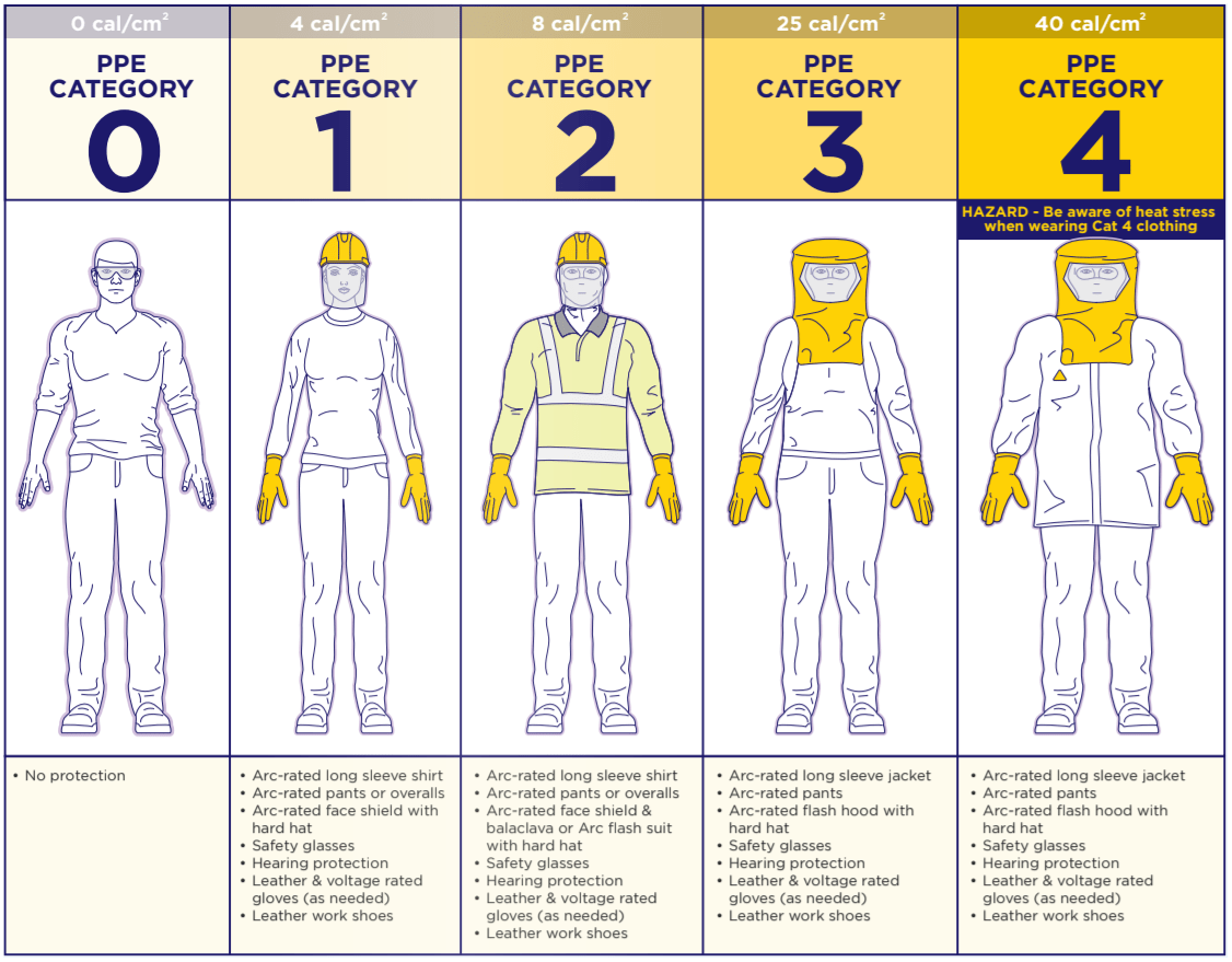
The NFPA 70E-2021 [5] and Electrical Arc Flash Hazard Management Guideline [6] provide PPE categories which are classified based on incident energy. The propriate PPE is supposed to be selected according to the calculated incident energy.
The NFPA 70E-2021[5] provides three different categories – for incident energy analysis method, for PPE category method and simplified category for PPE category method.
PPE Categories with Respect to Incident Energies [ref. 6] shown below.
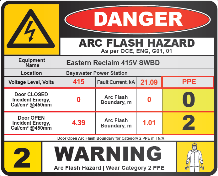
Arc Flash Warning Labels
An Arc Flash Hazard warning label must be affixed to the equipment and readily accessible to employees who may work on the energised equipment.
The basic requirements from the relevant guidelines are as follows.
Electrical Arc Flash Hazard Management Guideline
The items listed below are the minimum details that should be included in the label:
- Bus name or equipment name
- Bus voltage level
- Activity to be performed
- Incident energy level
- Arc flash boundaries
- PPE level required for varying activity and switchboard status (for example door open/ door closed).
- PPE – which protect people from the incident energy if all other controls fail and an arc flash occurs.
NFPA 70E-2021 (Section 130.5 (H) Equipment labelling)
The label should contain:
- Nominal system voltage
- Arc flash boundary
- At least one of the following (but not both):
- Available incident energy and the corresponding working distance; or
- Arc flash PPE category obtained from the ‘PPE category method’ for the equipment
- Minimum arc rating of clothing
- Site-specific level of PPE
Arc Flash Hazard warning label example [ref. 6] shown below.
References:
[1] The Other Electrical Hazard: Electric Arc Blast Burns, Lee, R. IEEE Transactions on Industry Applications, 1982.
[2] Predicting Incident Energy to Better Manage the Electric Arc Hazard on 600-V Power Distribution Systems, IEEE Transactions on Industry Applications, 2000.
[3] ENA NENS 09-2014, National Guideline for the Selection, Use and Maintenance of Personal Protection Equipment for Electrical Arc Hazards.
[4] IEEE Std. 1584-2018, IEEE Guide for Performing Arc-Flash Hazard Calculations.
[5] NFPA 70E-2021, Standard for Electrical Safety in the Workplace.
[6] Electrical Arc Flash Hazard Management Guideline-2019.

