Table of Contents
Overview
Proper safety standards must be adhered to while operating electrical systems. Faults such as arc flash can become dangerous enough to cause severe damage to people and property, even death in some cases. Arc flash occurs when current flows through the air between phase conductors, causing a large amount of thermal energy to be dissipated as radiant, convective, and conductive heat.
The human skin is prone to second-degree burns when exposed to incident energies greater than 1.2 cal/cm2. This is why it is essential to conduct arc flash studies while designing protection systems and selecting personal protective equipment (PPE) to safeguard personnel working on electrical equipment.
Different standards use different methods to calculate the arc flash incident energies and current, and different working distance requirements are required.
In this article, a complete AC arc flash calculation for an industrial installation is explained step-by-step.
IEEE Standard 1584 Method and Limitations
The IEEE 1584-2018 [1] provides an analytical process to calculate the arc current, incident energy, and arc flash boundary for arc flash analysis. This method can be used for the following system voltages and bolted fault currents,
Three-phase AC systems with voltages from 208 V to 15 kV
Bolted fault currents between 500 A to 106 kA (for 3-phase voltages 208 V to 600 V)
Bolted fault currents between 200 A to 65 kA (for 3-phase voltages 601 V to 15 kV)
Example Arc Flash Calculation
Consider a Low Voltage (LV) system that receives supply from an 11/0.4 kV, 250 kVA transformer at the Main Switchboard through a single core, 185 mm2 Cu cable. It is connected to a distribution switchboard through a single core, 95 mm2 Cu cable. Loads 0 & 1, each with a 45 A current rating, are fed from the distribution switchboard through single core, 16 mm2 Cu cables. The primary fault level is 15 kA. The system is modelled in the LV Network Calculator of ELEK Cable Pro Web Software; a single-line diagram of the described network is shown in Figure 1.
![Figure 1. Single-line diagram of the electrical system from ELEK Cable Pro Web Software [4]
A single line diagram is displayed on a screen, showing a transformer connected to a main switchboard, distribution switchboard, and load components. Options for export and live chat are visible on the interface.](https://eq8y3wpwe77.exactdn.com/wp-content/uploads/2024/09/Arc_Flash_Calculation_1-1170x585.png?strip=all&lossy=1&ssl=1)
Required Inputs for an Arc Flash Study (IEEE 1584:2018)
Working Distance
Working distance is the minimum distance between electrical equipment, conductors, and personnel to ensure safety. IEEE 1584:2018 [1] recommends a minimum working distance of 304.8 mm (12 in). Anything smaller could place the worker within range of the arc plasma cloud and metal droplets.
If the working distance is unknown, users can refer to the typical working distances for different equipment classes specified in IEEE 1584:2018 [1], as shown in Figure 2. These are meant to be guidelines, and alternate working distances may be used depending on the task being performed.
![Figure 2. Classes of equipment and typical working distances from [1]
A table showing equipment classes with corresponding working distances in millimeters and inches. Rows for "Low-voltage switchgear" and "Shallow low-voltage MCCs and panelboards" are highlighted in red.](https://eq8y3wpwe77.exactdn.com/wp-content/uploads/2024/09/Arc_Flash_Calculation_2.png?strip=all&lossy=1&ssl=1)
Electrode Configuration
Other essential factors the IEEE 1584:2018 [1] arc flash calculations consider are the effects of the electrode, electrode configuration, and enclosure dimensions on the arc. The construction of the enclosure can decrease or increase the severity of the arc flash to a certain extent, and realistic values of incident energy at the working distance must be considered when calculating the An excessive amount of incident energy would lead to a higher arc flash boundary and PPE requirements that may not be achievable.
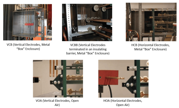
The different electrode configurations as per IEEE are VCB (Vertical Electrodes, Metal “Box” Enclosure), VCBB (Vertical Electrodes terminated in an insulating barrier, Metal “Box” Enclosure), HCB (Horizontal Electrodes, Metal “Box” Enclosure), VOA (Vertical Electrodes, Open Air) and HOA (Horizontal Electrodes, Open Air) as shown in Figure 3.

Electrode Gap and Enclosure Dimensions
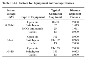
The gap between the conductor electrodes is smaller in low-voltage equipment and longer in medium and high-voltage equipment. Figure 4 gives the typical electrode gap and enclosure sizes for the IEEE 1584:2018 [1] arc flash model. It is preferable to use the actual gap measurements of the installed equipment, which are not always available. In that case, the typical gap measurements may provide approximately correct values. Alternatively, the user may refer to the typical gaps in NFPA 70E: Standard for Electrical Safety in the Workplace [2], shown in Figure 5.
In this example, the main distribution board has an electrode gap of 32 mm, and the distribution board has a gap of 25 mm, as per the IEEE 1584 table. The corresponding enclosure sizes, 508 mm x 508 mm x 508 mm and 355.6 mm x 304.8 mm x 203.5 mm, are selected for the main and distribution switchboards, respectively.


Supply Voltage
The supply voltage is the three-phase AC voltage at the switchgear, which in this example is 400 V.
Bolted Fault Current
A fault level study or calculation can determine the bolted fault current. Typical fault current levels as per IEEE 1584: 2018 [1] are as follows:
208 to 600 V: up to 106 kA
601 to 15 kV: up to 65 kA
The prospective bolt fault currents are already defined for each switchboard in the problem.
Bolted fault current at the Main Switchboard = 7.56 kA
Bolted fault current at the Distribution Switchboard = 5.70 kA
Arc Duration
The arc duration is taken from the switchboard protective device’s time-current characteristics when the arcing current is tripped. This depends on the type of protective device—MCB, MCCB, ACB, or fuse—and the device settings. Hence, having this information before proceeding with arc flash calculations is very important. The following devices are used for each switchboard under study:
Main Switchboard: Generic ACB, 160-400 A, Electronic LSI
Distribution Switchboard: Generic ACB, 100-250 A, Electronic LSI
If no protective device is present or the fault is not cleared by the protective device, a maximum arcing duration of 2 seconds is considered. This is based on clause 6.9.1 of IEEE 1584:2018 [1], which states that 2 seconds is a fair assumption of how long a person is likely to move away from the location of the arc flash.
![Figure 6. Time-current curves of Main and Distribution switchboard protective devices [4]
A line graph displaying upstream and downstream current (A) with trip points indicated. Red segments represent the Main Switchboard, while blue segments represent the Dist Switchboard.](https://eq8y3wpwe77.exactdn.com/wp-content/uploads/2024/09/Arc_Flash_Calculation_6.png?strip=all&lossy=1&ssl=1)
For the example under consideration, the fault clearing time based on the time-current curve for both switchboards is 110 ms. This means that when the prospective fault current occurs for the main switchboard (7.56 kA) and the distribution switchboard (5.70 kA), the protective devices will take 110 ms to trip and clear the fault.
Reduced Arc Duration
IEEE 1584:2018 [1] also calculates a reduced arcing current and incident energy. This is to account for the arcing current variation effect on the operation of the protective devices. The protective devices are set to trip faster as the fault current increases. Conversely, a lower arcing current would take longer to trip the OCPD, with a longer arc duration. As a result, the incident energy (= arcing current2 * time) may be higher and more dangerous to personnel. Thus, more stringent personal protective equipment (PPE) would be required.
The incident energy and arc-flash boundary results obtained using the arcing current & reduced arcing current may differ. The final incident energy or arc-flash boundary is the higher of the two calculated values.
Results of the Arc Flash Study
Arcing Current, Incident Energy, and Arc Flash Boundary Results
Table 1 below shows the arc flash results for the main and distribution switchboards.
Table 1. Arc Flash Calculation Results
| Parameter | Main Switchboard | Distribution Switchboard | Arc Flash Boundary (mm) |
|---|---|---|
| 451 | 279 | |
| Arc Flash Boundary (mm) | 490 | 302 |
| Incident Energy (cal/cm2) | 0.743 | 0.544 |
| Incident Energy (cal/cm2) | 0.846 | 0.620 |
| Reduced Arcing Current (kA) | 4.424 | 3.389 |
| Arcing Current (kA) | 5.071 | 3.885 |
| PPE Requirements | Category 1 | Category 1 |
Arcing current and reduced arcing currents and corresponding incident energies are calculated. Incident energy is lesser for the distribution switchboards as the bolted fault current is less. Accordingly, the arc flash boundary for the distribution switchboards is also lesser. In this example, the switchboards specify the same category and arc rating for PPE. It is also possible that different switchboards have different PPE requirements based on the calculated incident energies.
Personal Protective Equipment (PPE)
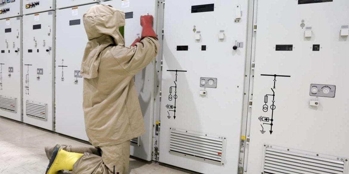
Personal protective equipment (PPE), such as arc-rated shirts, overalls, face shields, safety glasses, etc., protects personnel exposed to potential arc flashes. The minimum PPE requirements depend on the calculated incident energy. To specify conservative PPE requirements, IEEE 1584:2018 [1] uses the highest incident energies calculated for arcing and reduced arcing currents.
The IEEE 1584:2018 [1] method computes the incident energy and determines the arc flash boundary (AFB). The AFB signifies the distance from the arc source at which the incident energy reaches 5 J/cm2 (equivalent to 1.2 cal/cm2). This distance is the minimum working distance for equipment, representing the space between the arc source and personnel exposed to it, which is essential for preventing injuries. This is based on the understanding that incident energies exceeding 5 J/cm2 can potentially cause second-degree burns.
For the example problem, the calculated incident energies are:
Main Switchboard: 0.846 cal/cm2
Distribution Switchboard: 0.620 cal/cm2
The Electrical Arc Flash Hazard Management Guideline [3] is used as the category source for the PPE. Under this guideline, the main and distribution switchboards both fall under Category 1 of the PPE categories, which specify PPE for incident energies up to 4 cal/cm2.
Category 1 requires the use of the following PPE:
Arc-rated long-sleeve shirt
Arc-rated pants or overalls
Arc-rated face shield with hard hat
Safety glasses
Hearing protection
Leather & voltage rated gloves (as needed)
Leather work shoes
Personal Protective Equipment (PPE)
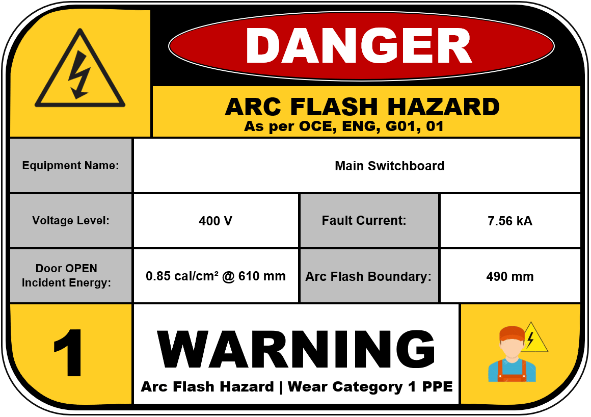
The Arc Flash warning labels are also generated based on the PPE category under which the equipment falls. The template depends on the reference standard. For this problem, the Electrical Arc Flash Hazard Management Guideline [3] template will be used.
Figures 7 and 8 show the Arc Flash warning labels required for the main and distribution switchboards, considering the results of the Arc Flash Calculation.


Recommendations
A short-circuit study is a pre-requisite to an arc flash calculation since calculated arcing currents, and incident energies depend on the prospective short-circuit current that would occur on a switchboard.
The results of a protection coordination study are also preferably available before arc flash calculations since the protective device settings will determine the fault-clearing time for each switchboard, determining the arc duration. If no protection coordination study is available, a maximum arc duration of 2 seconds can be considered based on IEEE 1584:2018 [1].
Performing arc flash calculations will help determine the areas at high risk of arc flash. The results of which help in determining the following:
Establish protection boundaries (arc flash boundaries) where second-degree burns would likely occur
Identify proper warning labels to mitigate the existing risks from the energised equipment
Determine adequate Personal Protective Equipment (PPE) to prevent injuries
IEEE 1584:2018 [1] also has additional procedures to calculate arcing currents and incident energies based on a reduced arc duration, mostly due to the varying response times of protective devices. This is to consider that higher fault levels trip devices faster and vice versa, which might result in a higher incident energy (I2t). Both arcing current and duration have direct proportionalities to incident energy. The higher values for incident energy and arc flash boundary from the arcing current and reduced arcing current will be used as the final values.
The LV Network Calculator of ELEK Cable Pro Web can perform arc flash calculations for a modelled network. Short-circuit currents for each equipment are automatically calculated based on the fault level at the source as it propagates downstream. Arc durations are also based on the protection settings of the relevant protection devices.
Tips and Suggestions
If shop drawings of the switchgear are unavailable, IEEE 1584:2018 [1] may provide typical values of working distances, electrode gaps, and enclosure sizes.
In cases where data regarding protection settings and fault-clearing times are unknown, a conservative arc duration of 2 seconds can be considered for calculations.
Calculations must also consider reduced arc durations, which may result in higher incident energies and arc flash boundaries. In that case, a higher PPE category and warning label might be required. An increased arc flash boundary might also be recommended.
References
[1] IEEE 1584:2018: IEEE Guide for Performing Arc-Flash Hazard Calculations
[2] NFPA 70E: Standard for Electrical Safety in the Workplace
[3] Electrical Arc Flash Hazard Management Guideline
[4] ELEK Cable Pro Web Software, Version 7.0 (2024).


