Introduction
The software used for calculating the results was ELEK LineRate Software.
Conductors Examined
Common Parameters
| Conductor: | |
|---|---|
| Maximum continuous operating temperature | 90 ˚C |
| Maximum short-time operating temperature | 160 ˚C |
| Initial conductor temperature prior to transient | 50 ˚C |
| Environmental conditions: | |
| Ambient air temperature | 40 ˚C |
| Wind velocity | 1 m/s |
| Wind angle relative to conductor axis | 90 degrees |
| Elevation above sea level | 10 m |
| Solar radiation intensity | 0 W/m2 |
| Solar absorption coefficient | 0.5 |
| Surface emissivity coefficient | 0.5 |
Steady-State Conditions
The flow of current in a conductor causes its temperature to rise due to the effects of joule heating, the magnetic and skin effects.
Figure 1 shows as current flow in a conductor increases so does the operating temperature.

Joule heating refers to the heating of the conductor due to the electrical resistance which varies with frequency, average current density and temperature.
Increasing the wind speed improves the rate of convection of heat away from the conductor which increases the current rating.
A small change of wind speed results in a relatively large change of current rating (Figure 2).
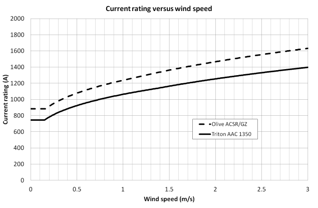
There are two main components to convection causing the drawing of heat away from the conductor; natural and forced convection.
The natural convection component (constant) is dominant only up until the wind speed exceeds a certain low value.
This is evident from the initial flat section of the curves shown by Figure 2 above.
Figure 3 shows that current rating increases significantly as wind incident angle relative to the conductor axis approaches 90˚ (perpendicular wind).

The angle of the wind incident on the surface of a conductor influences the heat loss due to forced convection.
The wind direction multiplying factor from [1] which is a sinusoidal function varies between 0.388 and 1 for θ = 0˚ and θ = 90˚ respectively, and is defined as:
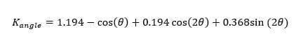
Where
θ is the angle between the wind direction and the conductor axis.
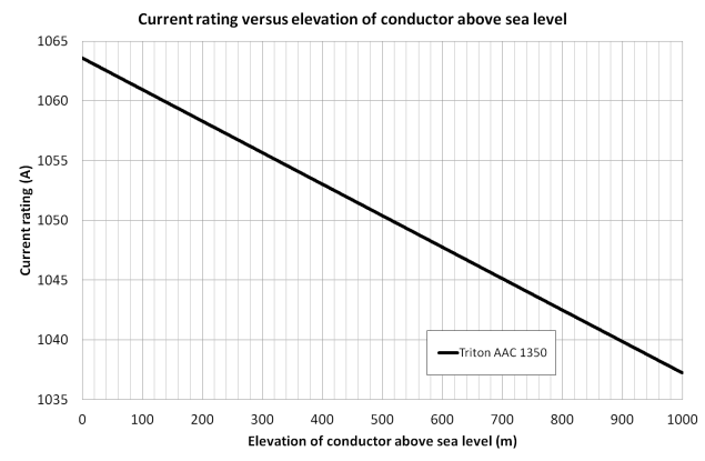
Elevation above sea level
Both natural and forced convection heat loss are dependent on the density of the air which is inversely proportional to elevation above sea level.
Figure 4 shows as the elevation above sea level increases the current rating slightly decreases (< 3%) due to a reduction in air density resulting in convection heat loss being not as effective.
Solar radiation intensity
Figure 5 shows that as solar radiation intensity increases conductor current rating goes down. Solar heating of a conductor is linear and independent of conductor temperature. For the same absorption coefficient (0.5 in this case) the reduction in current rating depends on the size of the exposed surface area of the conductor. For example, the rate of reduction in current rating due to increasing solar radiation intensity (refer to the slope of the equations of the linear curves in Figure 5) for the Olive ACSR/GZ conductor is greater due to its larger diameter and hence surface area compared to the Triton AAC conductor.

The heat gain rate from the sun depends on the effective surface area exposed, solar radiation intensity and the absorptivity of the conductor surface.
The intensity of solar radiation can be calculated depending upon the latitude and altitude of the conductor as well as the time of year and sky conditions.
For daytime ratings of conductors a typically conservative approach is to rate a conductor assuming that high solar radiation levels coincide with very low wind speeds.
However, this approach may not be correct since studies have shown that minimum wind speeds are three times greater due to the effects of thermals when the sun is shining [6].
Transient Conditions
Note it is assumed that the weather parameters remain constant for the duration of the transient.
Step increase in current
The transient responses to a step increase in current are shown in Figure 6. Both conductors are initially carrying (different) currents maintaining a constant operating temperature of 55 ˚C. A step in current is applied causing the temperature to rise to approximately 90 ˚C (full-load).
The variation in conductor temperature with time over the first 60 minutes is approximately exponential.
The rate-of-rise of temperature of the Olive ACSR/GZ conductor is lower than the Triton AAC. This is due to the higher conductor heat capacity (thermal inertia) which is the sum of the products of the specific heat and mass per unit length of the components of the conductor.
The transient current rating of a conductor is the determination of the current which causes the conductor temperature to reach its maximum allowable value in the allotted time. Figure 7 shows that the transient current rating is highly dependent on the duration of the transient.
For example, for a 1 second duration transient the (short-circuit) current rating of the Olive ACSR/GZ conductor is 51933 A.
As the duration of the transient increases the curves for both conductors converge with their steady-state current rating values.
Radial Conductor Temperature

The thermal conductivity of solid aluminium is around 237 W/m-˚C. However, conventional overhead conductors consist of aluminium circular or trapezoidal strands and core strands with air gaps between them. These air gaps hinder the flow of heat and the contact surfaces of the strands also increases thermal resistance. This leads to an apparent or effective radial thermal conductivity which is much lower (typically in the range of 0.5 – 4 W/m-˚C [3]). Other results have shown conductors under tension have higher effective radial thermal conductivity of around 1.5 W/m-˚C than slack conductors (which in the field can be caused by plastic or thermal elongation) around 0.7 W/m-˚C [5].
Conclusion
Changing the following factors affects the current rating for bare conductors in the following ways:
- Temperature – increased temperature increases electrical resistance.
- Frequency – increased frequency increases the losses from the skin effect.
- Wind speed and direction – higher wind speeds significantly improve the convection of heat away from the conductor. Perpendicular wind is most effective.
- Elevation above sea level – conductors installed nearer to the sea level have slightly improved current ratings due to higher air density.
- Solar radiation – the sun reduces the current rating of conductors.
At or near to full rated current the temperature of the core can be significantly higher than the conductor surface.
In this case the effects on conductor sag and mechanical degradation should be considered.
Appendix – Conductor Data
Physical and electrical properties are required for modelling. The following conductor data was taken from the Pirelli Overhead Conductor Catalogue [8].
| Physical properties | Value |
|---|---|
| Type | AAC |
| Stranding and wire diameter (No./mm) | 37/3.75 |
| Nominal overall diameter (mm) | 26.3 |
| Total mass (kg/km) | 1130 |
| Electrical properties (50 Hz) | Value |
| D.c. resistance at 20 ˚C (Ω/km) | 0.0701 |
| A.c. resistance at 75 ˚ (Ω/km) | 0.087 |
| Physical properties | Value |
|---|---|
| Type | ACSR |
| Code name | Olive |
| Stranding and wire diameter (No. cond. strands/No. core strands/mm) | 54/7/3.5 |
| Nominal overall diameter (mm) | 31.5 |
| Total mass (kg/km) | 1960 |
| Electrical properties (50 Hz) | Value |
| D.c. resistance at 20 ˚C (Ω/km) | 0.0557 |
| A.c. resistance at 75 ˚ (Ω/km) | 0.0716 |
References
- IEEE Std. 738-2006, “IEEE Standard for Calculating the Current-Temperature of Bare Overhead Conductors.”
- IEEE Std. 738-2012 Draft 10, “IEEE Standard for Calculating the Current-Temperature of Bare Overhead Conductors.”
- CIGRE WG 22.12, “Thermal Behaviour of Overhead Conductors”, Technical Brochure 207, August 2002.
- CIGRE WG B2.12, “Guide for Selection of Weather Parameters for Bare Overhead Conductor Ratings”, Technical Brochure 299, August 2006.
- CIGRE WG B2-108, “Radial and Longitudinal Temperature Gradients in Bare Stranded Conductors with High Current Densities”, 2012.
- C.F. Price and R.R. Gibbon, “Statistical approach to thermal rating of overhead lines for power transmission and distribution”, IEE Proceedings, Vol. 130, Pt. C, No. 5, Sept. 1983.
- Aluminium Electrical Conductor Handbook, 3rd edition 1989, The Aluminium Association.
- Pirelli Overhead Conductor Catalogue.