Table of Contents
Introduction
Current standards for cable trench design lack guidance for complex installation conditions and parameter interactions that influence thermal performance. This article demonstrates how optimising cable separation and applying engineered backfill can significantly improve cable ampacity, providing both theoretical analysis and practical trench design procedures.
Cable Trench Design Considerations for Solar PV Systems
Video Overview: This video explains the key trench design factors that influence cable ampacity and overheating in solar PV installations, building on the engineering insights in this article.
Presentation Slides
Download the full PDF slide deck of this article for your reference.
This article presents a comprehensive analysis of thermal behaviour in solar inverter cable trenches through a detailed case study using the cable model in a real-world solar farm. The analysis demonstrates quantifiable relationships between design choices and ampacity improvements, providing engineers with practical insights for optimising trench designs. The conclusion and the trench design procedure are also provided, which is useful and valuable for practical purposes.
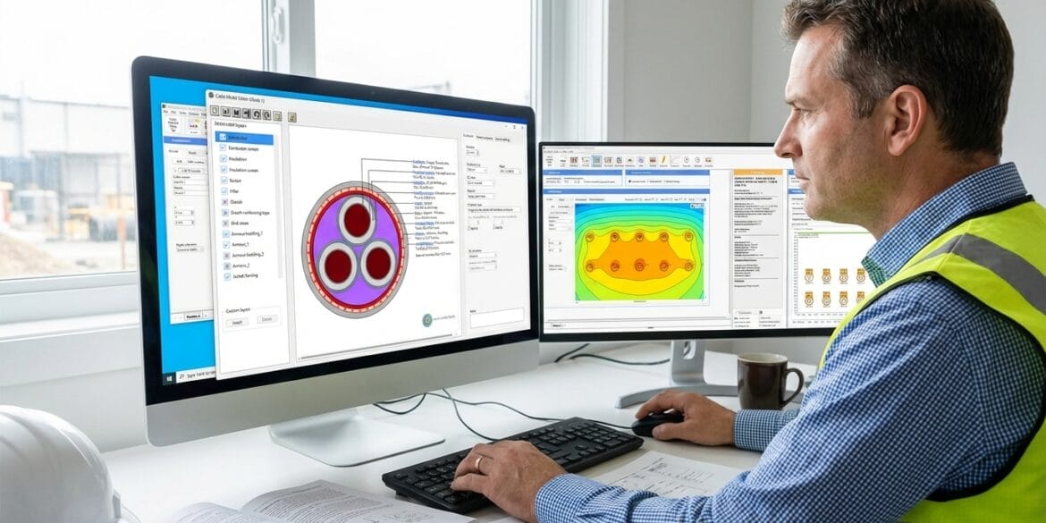
Modelling was performed using ELEK Cable HV Software™, which utilises calculations based on the IEC 60287 standards [1], equations published by Neher and McGrath, and the finite element method.
Case Study — Solar Farm Cable Overheating and Failures
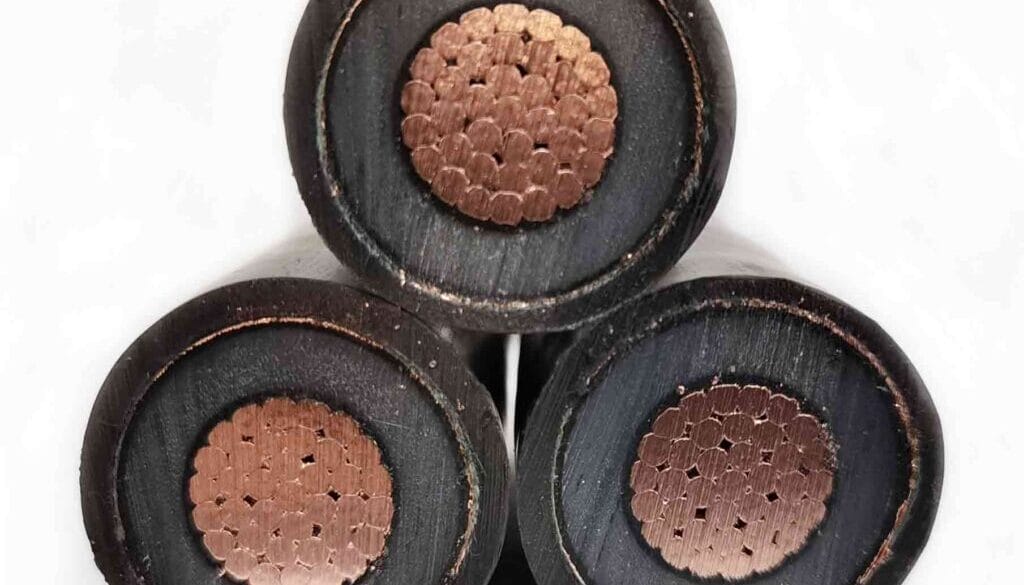
The installation used 4/0 AL cables in ducts, buried in trenches and was required to carry 120 A due to the specifications of their solar farm inverters. The problem was that they found their cables were overheating and operating well above the cable’s temperature limit of 90°C.

Current electrical standards for solar PV cables cover only the basic requirements, including the minimum burial depth, mechanical protection, cable types, warning tape, and separation from other services. However, they fail to address installation concerns in modern solar farms. They do not provide guidance for large, multi-circuit trenches, such as those with 10–60 circuits in solar installations. Additionally, the standards cannot account for non-unity load factors, soil dry-out conditions, or engineered backfill effects, leaving the problem of overheating complicated to solve.
Trench Design Variables that Determine Ampacity

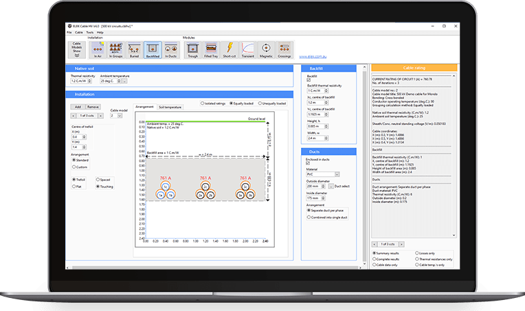
We analyse the impact of circuit separation on cable ampacity across native soils with varying thermal resistivities and under dry-out soil conditions. Additionally, the benefits of the backfill are involved. The ampacity-circuit separation characteristics under different installation conditions are shown in Figure 3, with the following observations:
- Ampacity increases with separation due to reduced mutual heating; however, the improvement diminishes with increasing distances.
- Low soil TR improves ampacity irrespective of the separation between circuits.
- In dry soil conditions (high TR), engineered backfill provides significantly higher ampacity improvement than increasing cable separation alone.
- Backfill maximises ampacity gains at narrow cable spacing but becomes counterproductive at wide spacing due to increased mutual heating between cables.

Core Principles for Reliable Solar PV Cable Trench Design
The key takeaways that can practically help with the solar PV cables trench design are as follows:
- Model the trench before the cables are installed.
- Measure soil TR for the location.
- Higher soil thermal resistivity and temperature decrease ampacity.
- Wider cable spacing improves ampacity but with progressively smaller gains at larger separations.
- Increasing cable separation provides similar ampacity improvements, regardless of soil TR.
- In dry soil conditions, backfill installation is more effective than increasing cable separation.
- Engineered backfill is more effective at narrow cable/circuit spacings.
- Low-TR backfill can become counterproductive at large separations due to mutual heat.
Furthermore, our recommended cable trench design procedure is shown in Figure 4.

Essential Trench Design Principles
The fundamental relationship between cable losses and temperature rise
Heat produced in a cable is proportional to the square of the current:
The temperature of the cable/circuit will rise accordingly, which follows:
\(\Delta \theta = WT\)
Where:
- W = Power losses per unit length [W/m]
- I = Current [A]
- R = Electrical resistance [Ω/m]
- Δθ = Temperature rise [°C]
- T = Total thermal resistance [K·m/W]
These two equations reveal that cable temperature is controlled by two factors you can influence: (i) Heat generation, which is controlled by cable size and current; (ii) Heat dissipation, which is controlled by separation, backfill, and soil conditions.
Mutual heating in solar farm trenches
Figure 5 illustrates the thermal distribution for three cable separation distances, demonstrating how mutual heating between cables reduces their ampacity. As separation increases, the thermal interference zones between cables decrease, allowing improved heat dissipation and higher ampacity. When engineered backfill is introduced, the overall ampacity increases due to enhanced heat dissipation.

Soil drying
where
Δθx: Total temperature rise, ∆θx0 ≥ 15 °C;
LF = load factor.

Conclusions and Recommendations
References:
[1] IEC 60287-1-1:2023 Electric Cables – Calculation of the current rating – Part 1-1: Current rating equations (100 % load factor) and calculation of losses – General. International Electrotechnical Commission.
[2] IEC 60287-2-1:2023 Electric cables – Calculation of the current rating – Part 2-1: Calculation of thermal resistance. International Electrotechnical Commission.
[3] VDE 0276-1000:2023, Power cables – Part 1000: Application guide for operation, VDE Verlag GmbH, Berlin.
Frequently Asked Questions
- What affects cable ampacity in solar PV trenches? Key factors include soil thermal resistivity, circuit spacing, engineered backfill, load factor, and dry-out effects. These variables interact and require thermal modelling to accurately determine ampacity.
- Do standards address soil dry-out in trench installations? IEC 60287 guides in considering the effects of soil drying on cable ampacity. This guidance needs to be applied in software modelling.
- When is engineered backfill more effective than increasing cable spacing? In high-TR soils or dry-out conditions, engineered backfill often improves ampacity more than additional spacing—especially when circuits are closely packed.
- What are the leading causes of cable failure in solar PV cable trenches? The leading cause is that the trenches are not correctly designed. The cables and their arrangement need to be modelled using a suitable software package. Cables installed in overcrowded trenches will overheat and fail.