Table of Contents
Overview
This paper describes the method and has examples for calculating the steady-state current rating of high voltage oil-filled cables buried in the ground. In the example calculation, the cable model has been built in software and the current rating was determined for a buried installation.
Oil-filled cable fundamentals
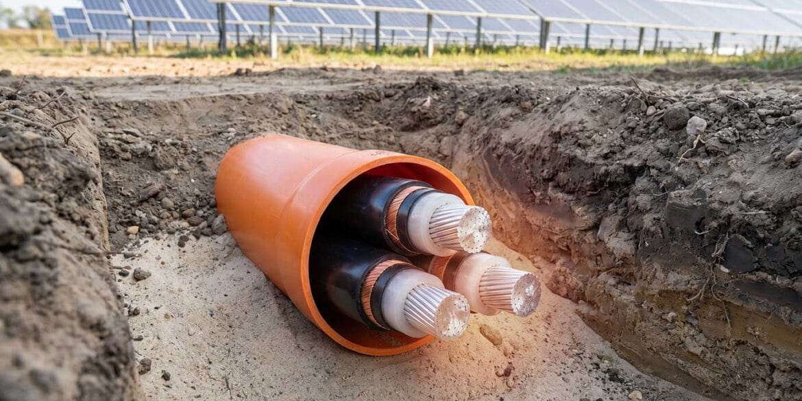
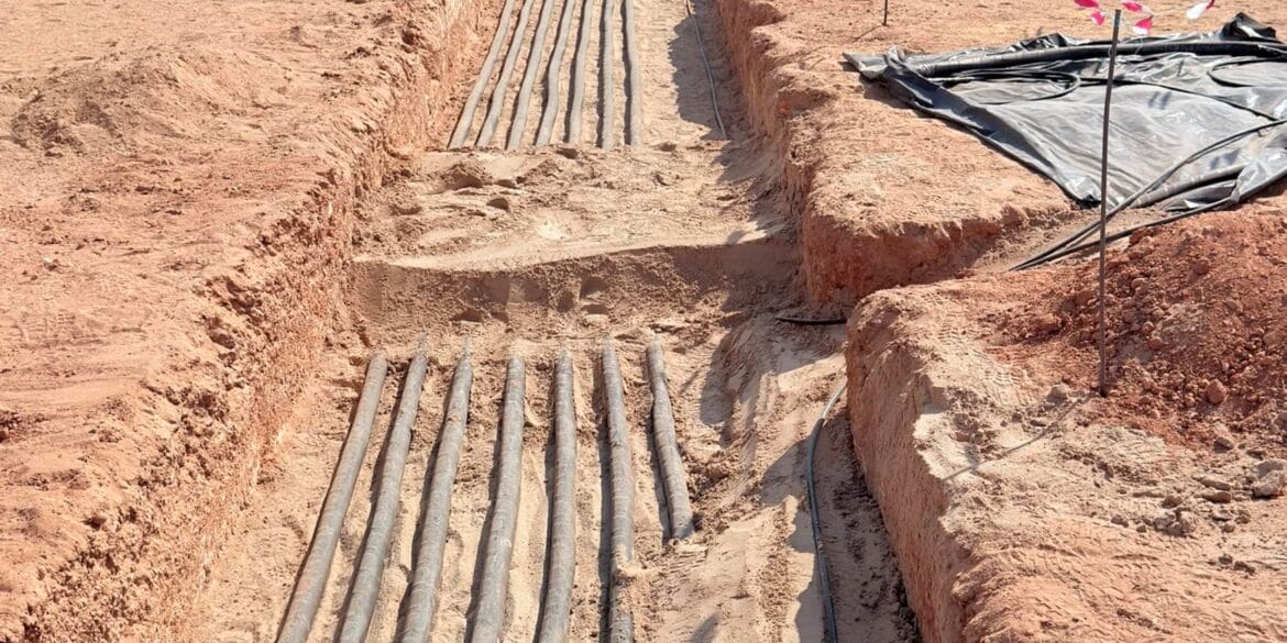
Oil-filled cables are a part of the self-contained fluid-filled cable type family. The main insulation for this type consists of multiple layers of paper impregnated with oil (to prevent the formation of voids and the ionisation of these voids during energisation) and encased in a metal sheath. Single core oil-filled cables have a central fluid duct that allows the oil (dielectric fluid) to flow along the cable length. Three-core oil-filled cables usually have multiple fluid ducts embedded in the filler material between the cores, or if there is no filler the oil flows between the insulation of the cores and the outer metal sheath. An outer sheath (or jacket) is provided to prevent corrosion of the metal sheath.
![Current Rating of High Voltage Oil-filled Cables Figure 1 Examples of oil filled single core and three core cables - Current Rating of High Voltage Oil-filled Cables](https://e6f7jzv78yj.exactdn.com/wp-content/uploads/2023/08/Figure-1-Examples-of-oil-filled-single-core-and-three-core-cables.png?strip=all&lossy=1&ssl=1)
Figure 1 – Examples of oil-filled single core and three-core cables
Current rating calculations for oil-filled cables
The Standard IEC 60287 [1] details a methodology to calculate the steady-state current rating for cables of all AC voltages and DC cables rated up to 5 kV. The IEC standard is extendable for HVDC cables (rated > 5 kV DC) by incorporating an electrical stress limited rating.
The IEC 60287 Standard, of which there are nine separate parts, provide detailed analytical equations for calculating current ratings. The steps to the current rating calculations are:
- Model the oil-filled cable using cable component dimensions and material properties obtained from a manufacturer datasheet. Oil duct dimensions and fluid properties are not required for the current rating calculations.
- Calculate the AC resistance of the conductor as operating temperature.
- Calculate the electrical loss factors from the metallic layers in the oil-filled cable. The electrical loss of the sheath depends on the bonding arrangement.
- Calculate the dielectric losses inside the main insulation determined by the insulation capacitance and operating voltage.
- Calculate the internal thermal resistances T1, T2, and T3 inside the oil-filled cable.
- Calculate the external thermal resistance T4 based on the external thermal environment and the installation conditions. Note this can be done using the analytical equations in IEC 60287-2-1 [1], or alternatively using numerical finite-element calculations.
Example calculation
Cable model
The cable model considered in this study is a 400 kV (50 Hz) single core cable with 2000 mm2 copper conductors as shown in Figure 1. The cable has an outer diameter of 142.8 mm.
The main insulation of this oil-filled cable was of complex laminated construction, consisting of three separate layers of paper materials with different thermal resistances. Therefore, the insulation in the software model shown below required multiple custom cable layers.
The maximum permissible operating temperature of the conductor is 85 ˚C.
![Oil-filled cable model image from ELEK Cable HV software Oil-filled cable model image from ELEK Cable HV software](https://e6f7jzv78yj.exactdn.com/wp-content/uploads/2023/08/Figure-2-Oil-filled-cable-manufacturer-datasheet-drawing-and-software-model.png?strip=all&lossy=1&ssl=1)
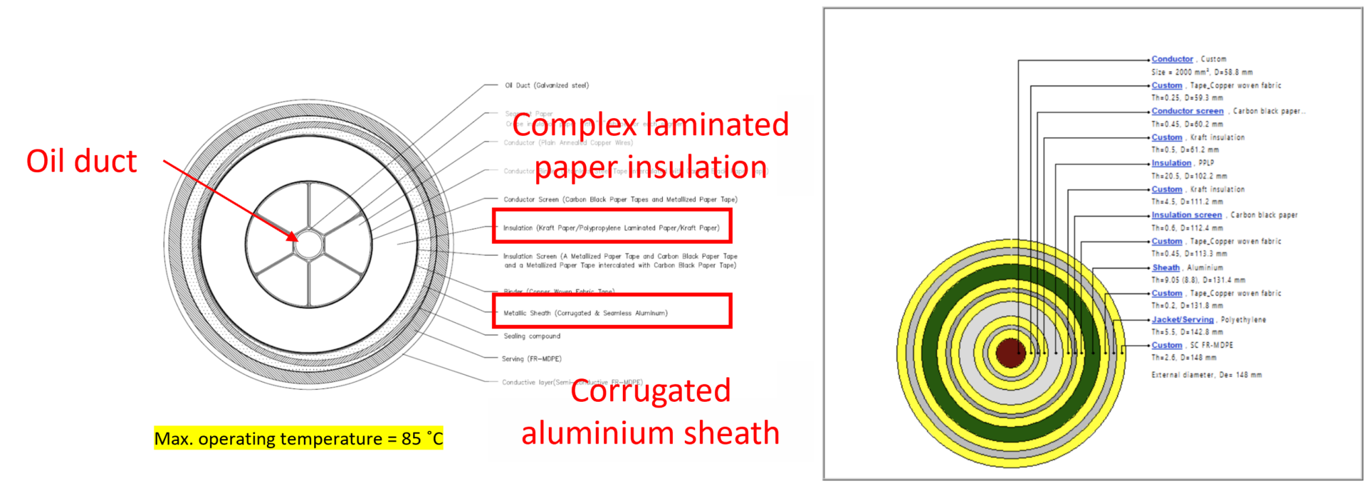
Figure 2 – Oil-filled cable software model
Installation conditions
The cables are installed (buried) as follows.
Table 1. Tunnel parameters
Parameter | Value | Unit |
---|---|---|
Operating voltage | 400 | kV |
Frequency | 50 | Hz |
Buried arrangement | Trefoil, touching | |
Burial depth (centre of trefoil) | 1 | m |
Sheath bonding | Solidly bonded | |
Native soil thermal resistivity | 1 | K.m/W |
Soil ambient temperature | 20 | ˚C |
Calculated cable current rating
The current rating of the oil-filled cables was calculated using the IEC 60287 Standard combined with the finite element technique.
![Current Rating of High Voltage Oil-filled Cables Figure 4 Oil filled cable rating finite element technique mesh plot - Current Rating of High Voltage Oil-filled Cables](https://e6f7jzv78yj.exactdn.com/wp-content/uploads/2023/08/Figure-4-Oil-filled-cable-rating-finite-element-technique-mesh-plot.png?strip=all&lossy=1&ssl=1)
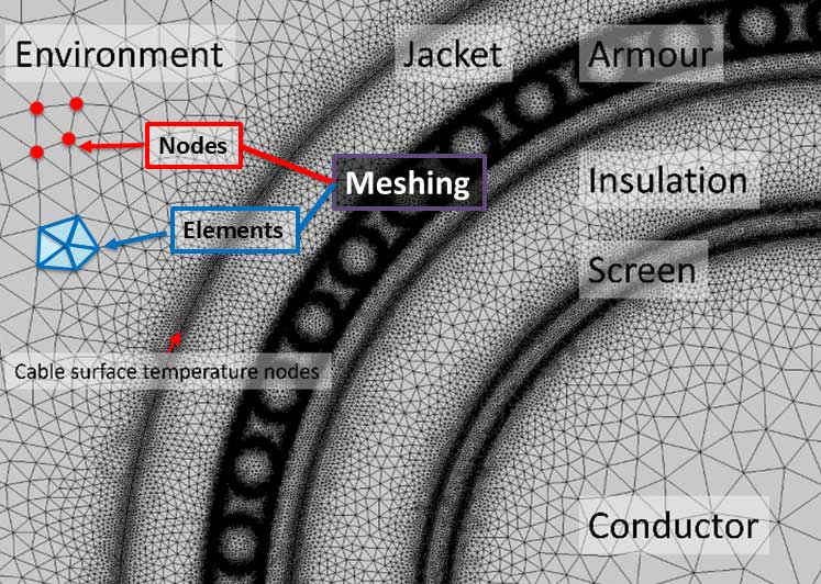
Figure 3 – Mesh plot from a finite element model of the oil-filled cables
The current rating of a single circuit is 850 A as shown in Figure 3. The sheath circulating currents were calculated to be 528 A.
![Current Rating of High Voltage Oil-filled Cables Figure 3 Oil filled cable current rating calculation result - Current Rating of High Voltage Oil-filled Cables](https://e6f7jzv78yj.exactdn.com/wp-content/uploads/2023/08/Figure-3-Oil-filled-cable-current-rating-calculation-result.png?strip=all&lossy=1&ssl=1)
Figure 4 – Oil-filled cable current rating calculation result
Conclusion
A current rating calculation of oil-filled cables has been demonstrated. The main challenge with performing current rating calculations for oil-filled cables is with the cable model. For example, the insulation may consist of multiple paper layers with different thermal properties and the dimensions and thermal properties of all the cable layers should be known. The IEC 60287 standard method is otherwise well-suited and straight-forward for oil-filled cable rating calculations. For better accuracy, and flexibility with the installation conditions, the finite element technique may be used for calculating the external thermal resistance of the cables.
References
[1] IEC 60287-1-1 Electric cables – Calculation of the current rating – Part 1-1: Current rating equations (100 % load factor) and calculation of losses – General
[2] IEC 60287-2-1 Electric cables – Calculation of the current rating – Part 2-1: Thermal resistance – Calculation of thermal resistance