Table of Contents
What causes induced sheath voltages inside cables?
The conductor of a high-voltage cable often carries currents of several hundred amperes. These AC currents create electromagnetic forces on metallic layers around them. A voltage is induced in the sheath of a high voltage (HV) cable primarily due to electromagnetic induction from the principal conductor, particularly in single-core cables carrying alternating current (AC). This effect results from the changing magnetic field surrounding the conductor, which induces a voltage in the nearby metallic sheath or armour. Voltages are induced on the sheaths of high voltage cables through two primary mechanisms: inductive coupling and capacitive coupling.
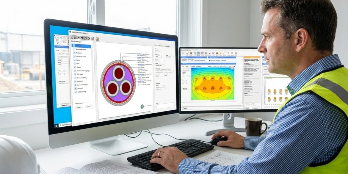
ELEK Cable HV Software can perform accurate induced sheath voltage calculations.
Inductive coupling inside cables
Inductive voltages arise from the electromagnetic field generated by the current flowing through the conductor. As the magnetic field fluctuates, it induces an electromotive force in the adjacent metallic sheath. This induced voltage is proportional to factors including the current’s magnitude, the operation frequency, the mutual inductance between conductor and sheath, and the physical arrangement of the cables in the circuits (e.g., spacing between the cables). Higher frequencies and closer proximity between conductor and sheath result in higher induced voltages.
Inductive coupling in HV cables involves mutual and self-inductance effects, which govern the magnitude and behaviour of induced sheath voltages.
Self-Inductance
Self-inductance refers to the property of any current-carrying conductor to produce its own magnetic field, which induces a voltage opposing changes in current (Lenz’s Law).
In practice, the sheath’s self-inductance mainly affects the impedance of the sheath and the distribution of circulating currents, rather than directly generating additional sheath voltage from the core’s current.
However, depending on the bonding arrangements, the sheath’s self-inductance plays a significant role in impedance calculations used to estimate sheath currents and losses.
Mutual Inductance
Mutual inductance is the property whereby a changing current in the core (main conductor) produces a time-varying magnetic field that links with the metallic sheath, inducing a voltage in the sheath.
The induced voltage (Vsh) in the sheath is directly proportional to:
The mutual inductance (XM) between core and sheath,
The operating current (I) in the core,
The frequency (f) and cable length (L).
The relationship is expressed as:
Where: XM=jωLM, with LM being the mutual inductivity per unit length and ω the angular frequency.
- The value of LM depends on physical factors such as the spacing between the core and sheath, cable diameter, and layout (e.g., trefoil or flat formation). Increasing the distance between core and sheath or between phases generally changes the mutual inductance, affecting the induced sheath voltage.
Combined Effects
The actual sheath voltage results from the superposition of the mutual inductive coupling from the core and the influence of the sheath’s self-inductance.
In multicable systems, mutual inductance can occur between each core and its own sheath and between adjacent cables (intersheath mutual inductance), leading to cross-coupling effects.
The induced voltage and current distribution are complex, as the mutual and self-inductive properties interact with cable resistance, layout, and system frequency.
Capacitive coupling inside cables
Capacitive coupling in HV cables occurs due to the electric field between the cable core and the metallic sheath and between the sheath and the ground. The core conductor and sheath form a cylindrical capacitor, with the cable’s insulation acting as the dielectric. When an AC voltage is applied to the core, a displacement current flows through this capacitor, inducing a voltage and current in the sheath even if there is no load current.
The magnitude of capacitive coupling depends on several factors:
The conductor and sheath diameters, insulation properties, and cable length determine the capacitance value.
The rate of change of voltage (dv/dt) on the core, meaning higher frequency or faster voltage variations, causes stronger capacitive currents.
The distance and arrangement between the core and sheath, and how well the sheath is grounded or bonded.
If the sheath has a finite impedance, this capacitive current can cause a voltage drop, contributing to the sheath’s rise. Capacitive coupling is especially significant in lightly loaded or unloaded cables, where inductive effects are minimal but capacitive charging currents remain.
Capacitive coupling also influences interference between cables and circuits through stray capacitance and can be mitigated by increasing physical separation, shielding, or careful cable layout design.
In summary, capacitive coupling transfers energy via electric fields in HV cables, generating displacement currents and voltages in the sheath proportional to the system voltage, cable geometry, and frequency.
Why do you need to calculate sheath voltages?
Induced voltages on conductive sheaths can reach levels hazardous to personnel, causing electric shock risk during maintenance or accidental contact.
Safety measures include controlling cable proximity, bonding/earthing strategies, and ensuring sheath voltage does not exceed safe limits.
Proper design reduces the risk of unexpected sheath voltages that could damage equipment or cause faults.
Effects of bonding on sheath voltages
Combined Effects
In a single-point bonded system for high-voltage cables, the cable sheaths of all three phases are bonded together and earthed at only one point, while the other end is left open. Single-point bonding significantly affects sheath voltages in power cable systems, primarily by controlling the flow of circulating currents and their associated voltage drops. Single-point bonding prevents circulating currents but causes a rising induced voltage along the cable length that must be carefully managed with voltage limiters and cable length restrictions.
Sheath voltages increase linearly along the cable length from the bonding point. At the bonded end, sheath voltage is zero, and at the remote end, sheath voltage reaches its maximum value. Single-point bonding is most effective for shorter cables where the induced sheath voltages remain within acceptable limits, typically used in transmission systems where minimising losses is critical.
Cross-bonded
Cross bonding (also called cross-point bonding) significantly and beneficially affects sheath voltages by creating a system that essentially cancels out induced voltages while minimising circulating currents. Cross-bonding involves dividing the cable route into sections (typically three equal lengths) and systematically transposing the sheath connections between sections. Each sheath is connected to a different phase position at each joint, creating a rotation pattern similar to conductor transposition in overhead lines.
Segmentation of Cable Sheath: The cable length is divided into equal sections, and the three phases’ sheaths are cyclically interconnected across these sections. This cyclic swapping of sheath connections ensures that the inductive voltages induced in each phase sheath, which are 120° out of phase due to the three-phase AC system, partially cancel each other out.
Reduced Induced Sheath Voltage: The net induced sheath voltage is significantly lowered by the vector summation of the induced sheath voltages in each minor section. This decreases the risk of high sheath voltages found in single-point bonding and thus reduces insulation stress and the likelihood of electrical discharge or damage.
Elimination of Circulating Currents: Unlike solid bonding, where high sheath circulating currents cause losses and heating, cross bonding minimises these currents as the induced voltages counterbalance across sections, improving cable efficiency and thermal performance.
Increased Cable Lengths: Cross-bonding allows for longer cable sections than single-point bonding because induced sheath voltages are controlled to acceptable limits, making it more suitable for long HV cable routes.
No Need for Earth Continuity Conductor (ECC): Since the sheaths act as the return path for capacitive and fault currents, the cross-bonding arrangement can eliminate the need for a separate ECC, reducing infrastructure complexity.
Use of Sheath Voltage Limiters (SVLs): Even with cross bonding, transient overvoltages may occur (e.g., switching or lightning surges), so SVLs are often installed at bonding link boxes to protect the sheath from overvoltages.
Equations for calculating induced sheath voltages
The self-inductance between the conductor and its sheath is given by
The mutual inductance between the conductor and the sheath of the adjacent is given by
The voltage drop is given by
where n is the number of cables
Why is the standing voltage dependent on the length, and the circulating current not?
Circulating current is determined by Ohm’s Law in a closed loop, not by voltage accumulation
Eloop is the net unbalanced EMF driving the circulation (V/m)
Zloop is the total impedance of the circulating current path (Ω/m)
•EMF scales with length: Longer cable → proportionally more induced EMF
•Impedance scales with length: Longer cable → proportionally higher loop impedance
•Ratio remains constant: EMF/Z stays approximately the same regardless of length
Standing voltage in cable systems is calculated based on Faraday’s Law of Electromagnetic Induction. Electric field represents the rate of change of voltage with distance as follows:
EMF is the net standing voltage (V/m)
jωL is the mutual inductance (H)
•Standing voltage is proportional to the total induced EMF along the cable length
•Longer cable = more EMF accumulation = higher voltage
•This is why single-point bonding becomes impractical for very long cables
Case Study - 330 kV Circuits in Parallel for Data Centre Connection
This study aims to calculate the sheath voltage on the double circuit system carrying 875 A each. The sheath standing voltage must also be calculated on the out-of-service circuit compared to the other circuit in service. The project is a dual 330 kV connection between substations for a data centre connection. The capacity is 500 MW, and the full load carried by one circuit would be 875 amps. The fault condition is 50kA for 1 second.
The cable used in this design is a 330 kV, 1600 mm2 cable, with a corrugated Aluminium sheath. The cables are cross-bonded without transposition, and the overall circuit length is 2.6 km. The individual minor section lengths are 870 m.
Cable Model
The cable used in this design is a 330 kV, 1600 mm2 Copper Milikken conductor cable.

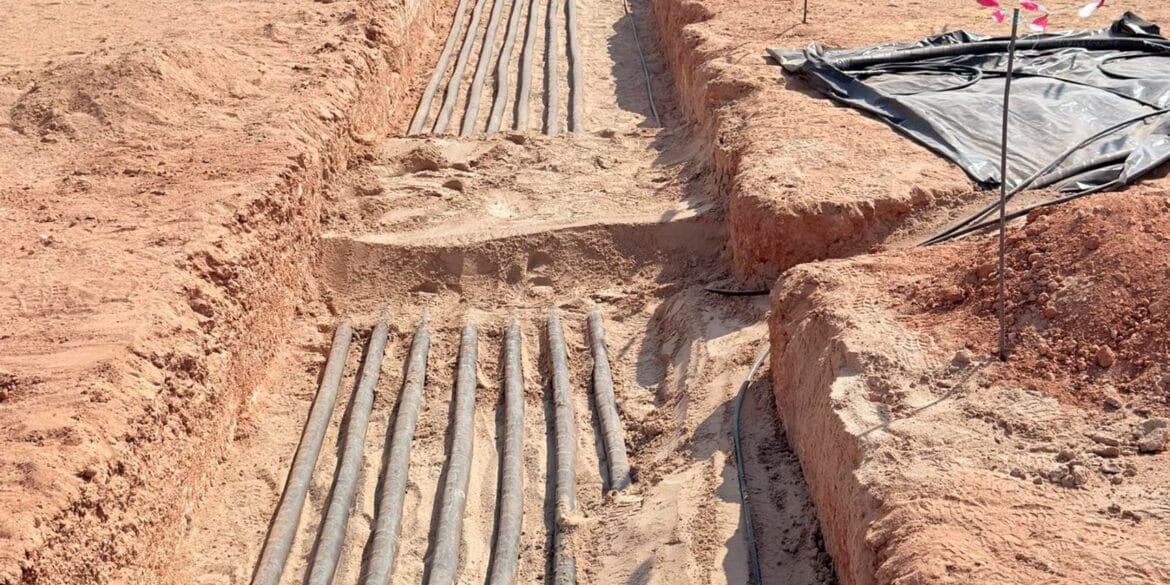
Installation
The cables are buried in individual trenches and arranged in a trefoil. The phase spacing of the individual circuits is 350 mm spacing [B], centre to centre. The trench widths are [D] 875mm. The spacing between the outer conduits of each circuit will be 2 metres (so the dimension [C] 2,875mm). Standard environmental conditions, such as soil thermal resistivity of 1.2 K.m/W and ambient temperature of 25 °C, are considered.

 and temperature (54°C and 55°C) values under ground level.")

Results
The case studies were done under two conditions.
-
Both circuits operate under normal operating conditions and carry a load current of 875 A each. The SVL design is carried out for a 50 kA fault current.
-
One circuit is out of service while the other carries the normal operating current. The SVL design is carried out for a 50 kA fault current on the in-service circuit.
The table below shows both circuits’ results under normal operation (875 A).
| Cable | Circuit 1 (V) | Circuit 2 (V) |
|---|---|---|
| A | 88.61 | 88.61 |
| B | 83.86 | 83.86 |
| C | 79.94 | 79.94 |
Under normal operating conditions, both circuits are assumed to carry 875 A. The mutual induction between the cables is significant due to the current rating and the separation between the circuits.
The table below shows the results for both circuits carrying the fault current (50 kA).
| Cable | Circuit 1 (kV) | Circuit 2 (kV) |
|---|---|---|
| A | 5.064 | 5.064 |
| B | 4.792 | 4.792 |
| C | 4.568 | 4.568 |
When the fault current of 50 kA flows through the circuits, the standing voltages significantly increase due to the high current magnitude.
One circuit is out of serviceThe second circuit is assumed to be out of service and does not carry any current. The first circuit operates under normal conditions and at fault.
The table below shows the results for both circuits when Circuit 2 is out of service.
| Cable | Circuit 1 (V) | Circuit 2 (V) |
|---|---|---|
| A | 84.07 | 5.31 |
| B | 84.06 | 5.06 |
| C | 84.07 | 4.71 |
Since circuit 2 is out of service, the mutual inductances between circuits are reduced. However, circuit 1 sees only a minor reduction in the sheath voltages as the coupling between cables within the same circuit is substantial.
The standing voltages on circuit 2 have been drastically reduced, as they are influenced only by the mutual induction created by circuit 1.
A similar trend can be seen when the fault current flows in only circuit 1 while the other is out of service.
| Cable | Circuit 1 (kV) | Circuit 2 (kV) |
|---|---|---|
| A | 4.804 | 0.304 |
| B | 4.804 | 0.289 |
| C | 4.804 | 0.269 |
Conclusions and Recommendations
Sheath voltages in HV cables depend on inductive and capacitive coupling effects, operating current, cable length, configuration, and bonding method.
Both operating mode (normal vs. fault conditions) and circuit status (both circuits in service vs. one out of service) strongly influence sheath voltages.
With both parallel circuits energised, mutual inductive coupling leads to significant standing and circulating voltages on each cable sheath, which increase further under fault conditions.
Taking one circuit out of service reduces the mutual coupling but does not eliminate induced voltage on the idle cable’s sheath—residual voltages persist and can become substantial during faults on the active circuit, posing safety risks during maintenance.
Cross-bonding of sheaths is the most effective strategy to minimise both circulating currents and standing sheath voltages, especially for long cable sections; it keeps induced voltages within acceptable and safe limits, unlike single-point bonding, where voltages can rise linearly to hazardous levels.
Proper specification and application of Sheath Voltage Limiters (SVLs) are essential to protect against transient overvoltages, especially under fault conditions.
Comprehensive bonding design, SVL protection, and awareness of induced voltages in energised and out-of-service cables are critical for maintaining operational safety and reliability in complex cable installations.