Table of Contents
How Cable Crossings Affect Current Rating
Cable crossings create local thermal hotspots. These can dictate the ampacity of an entire cable route. Evaluating the thermal risk and designing a safe and effective cable crossing is crucial. Both existing and new circuits must be checked. Geometry at the crossing point (crossing angle and vertical separation) usually determines the current rating of the circuits.
Why Cable Crossings Govern Ampacity
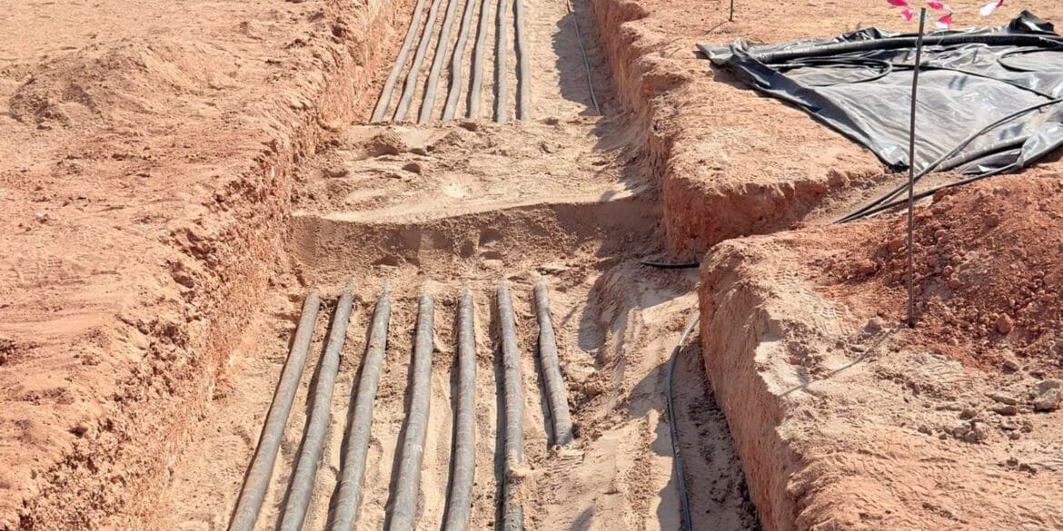
New cable circuits often need to be routed through areas where existing buried circuits are already in service. Frequently, when these new circuits are installed, they must cross below the existing circuits. Where these circuits cross, a local thermal bottleneck forms at the crossing point.
The hot spots that develop at these crossing points remove thermal margin and can dictate the ampacity of the entire cable route. The ampacity of cables at a crossing point is typically reduced by between 20% and 50%. Therefore, if a crossing point is not correctly accounted for, then the existing or crossing cables may overheat.
This article presents a comprehensive analysis of ampacity derating caused by cable crossings. A theory section explains the differences between regular parallel cable circuits and cable circuits that cross. The effects of crossing angle and vertical separation between crossing cables are presented. A detailed case study based on a real-world battery energy storage system (BESS) is given. A step-by-step procedure with a checklist for performing cable crossings studies is provided.
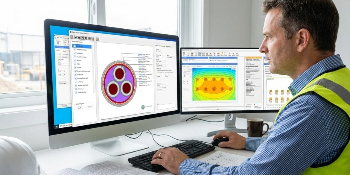
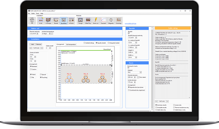
Modelling has been performed using ELEK Cable HV Software™.
Video Overview: This video provides an in-depth explanation of key ampacity considerations for crossing power cables, building on the information presented in this article.
Presentation Slides
Download the full PDF slide deck of this article for your reference.
Thermal Behaviour at Cable Crossings
At cable crossings, the thermal interaction between circuits is localised, producing a temperature peak at the crossing point rather than continuous heating along the route (Figure 1). This differs from the thermal behaviour of circuits in parallel, where heat is continuously distributed along the entire route (Figure 2).


Longitudinal Heat Flow and Length of Influence
Figure 3 provides an in-depth view of the temperature influence along a cable. At the crossing point, a temperature peak forms. Longitudinal heat flow transfers heat away from the crossing point in both directions along the circuits, reducing the peak temperature over a limited distance that depends on the soil thermal resistivity (TR). It also shows that the temperature rise for parallel cables is typically higher than for crossings, because the longitudinal heat flow reduces the peak temperature at the crossing.

Why Smaller Cables Are More Affected
Figure 4 illustrates an example where the derating factor of the smaller cables is 0.47, which is significantly lower than that of the larger circuit, which has a derating factor caused by the crossing point of 0.99 (i.e. its ampacity is virtually unaffected). This indicates that smaller or lower margin circuits will experience higher derating, as they heat up more for the same external heat and spread heat less effectively along the conductor. Meanwhile, the thermal contour plot on the right-hand side of Figure 4 demonstrates that the larger circuits dominate the surrounding soil temperature.

Vertical Separation at Cable Crossings
Vertical separation at small crossing angle:

Vertical separation at 90° crossing angle:
At a 90° crossing, the thermal interaction is highly localised, and the interaction length is minimal. As a result, changing vertical separation has a much smaller influence on derating. For the lower circuit, increased separation mainly increases burial depth, which can reduce ampacity and offset any reduction in mutual heating. This explains why the separation trends differ fundamentally from the small-angle case and why separation is far less effective at perpendicular crossings.

Increasing vertical separation reduces thermal interaction, but it also increases the burial depth of the new circuit. At shallow crossing angles, the reduction in thermal interaction dominates; at steep angles, increased burial depth becomes the dominant factor affecting ampacity.
Crossing Angle of Cable Circuits

Case Study — 33 kV HV Cable Crossing (BESS Example)
Parameters for modelling

The thermal interaction will derate the ampacity of both BESS systems. To determine if the circuits in both systems have sufficient ampacity after installing the BESS 2 circuits, a simulation should be conducted at two critical hot spots:
- The closest separation in parallel sections — where the existing and new circuits run side by side at minimum horizontal distance. This is where mutual heating is at its maximum.
- The crossing point — where the new circuits pass underneath the existing ones. This is the deepest burial point for the new cables.
Parallel Section Analysis – Closest Separation

Crossing Points Analysis

Practical Design Procedure for Cable Crossing Ampacity Studies
Cable crossing ampacity assessment should be treated as a structured hotspot analysis, not a single calculation. The objective is to demonstrate that both the existing circuit and the new circuit remain within their required current ratings at all thermally critical locations.
Step 1. Obtain Existing Circuit Information
Contact the owner of the existing circuit and obtain the design documentation, including cable datasheets (conductor size, material, configuration, and bonding), installation details (burial depth, spacing, and arrangement), and GIS or as-built location data. Confirm the operational constraints of the existing circuit, including operating current and maximum allowable conductor temperature. Environmental assumptions such as soil thermal resistivity and ambient soil temperature should be confirmed, with measured values preferred where available.
Step 2. Establish New Circuit Design
Define the new circuit cable selection and installation arrangement, including conductor size, construction, bonding, burial depth, and route geometry. Establish the required operating current and maximum conductor temperature limit for the new circuit, along with the assumed environmental conditions.
Step 3. Evaluate Parallel Sections (If Applicable)
Identify sections where the new and existing circuits run in parallel at their closest horizontal separation. Set up a thermal model representing this worst-case parallel condition and calculate the ampacity of both circuits. If either circuit does not meet its required current rating, mitigation measures such as increased separation or cable redesign must be considered before proceeding.
Step 4. Identify and Evaluate Crossing Points
Identify all locations where the new circuit crosses existing circuits. For each crossing, determine the crossing angle and vertical separation. Set up a thermal model of the crossing geometry and calculate conductor temperatures and ampacity for both circuits at the crossing point. Crossing points should be continuously assessed explicitly, as they often determine the overall current rating.
Step 5. Compare Hotspots and Establish Overall Current Rating
Compare the ampacity results from all analysed hotspots, including parallel sections and crossing points. The minimum ampacity value across all cases defines the overall current rating of the new circuit. Both the existing and new circuits must satisfy their own operational current requirements.
Step 6. Apply Mitigation If Required
If ampacity is insufficient for either circuit, mitigation should be applied in the following order:
- Increase the crossing angle to reduce the thermal interaction length.
- Increase the vertical separation to reduce mutual heating, considering the impact of increased burial depth on the new circuit.
- Review cable configuration or select a larger cable size with higher ampacity.
A summary of the design workflow, checklist, and technical notes for assessing buried cable crossing ampacity is provided in the one-page Buried Cable Crossing Ampacity Design Guide.

Key Engineering Takeaways
- Cable crossings create a local thermal hot spot at the crossing point.
- Longitudinal heat flow reduces the hot spot.
- Crossing angle is the dominant control and should be maximised.
- Separation distance is most effective at shallow crossing angles.
- Smaller cable circuits can be heavily derated at crossings.
Frequently Asked Questions
- Why doesn’t derating decrease when I increase the horizontal spacing between parallel circuits at a crossing?
Cable crossing calculations only consider the vertical separation between circuits and the angle of crossing. Horizontal spacing along the cable route has no effect because only a small section of cable (typically around 5 metres) at the crossing point contributes to mutual heating. - What crossing angle gives the best current rating?
A 90-degree (perpendicular) crossing gives the highest current rating with minimum derating. A 0-degree crossing (parallel cables) is the worst case. If cables run parallel in the same trench, they should be analysed as parallel circuits rather than as a crossing. - How does the calculation handle multiple circuits crossing at the same location?
Each circuit acts as a heat source, affecting the others. The calculation starts with each cable’s isolated rating and applies mutual heating based on the vertical distance and angle of each crossing circuit. The cable crossing calculations prescribed in IEC 60287 are limited to only two crossing circuits. However, if these calculation methods are extended to allow any number of circuits, such as in ELEK Cable HV Software, then any number of crossing circuits may be considered. - Can cyclic or emergency ratings be applied to crossing calculations?
Yes, but they are typically calculated separately. First, determine the cyclic rating factor (M factor) based on the daily load profile, as specified in IEC 60853 [3], and then apply it to the steady-state crossing rating. - What installation types can be analysed for crossings?
Crossings can be calculated for direct buried cables, cables in ducts, and cables in backfill. The key requirement is that all circuits use consistent thermal parameters at the point of intersection. - Can external heat sources like steam pipes be included?
Yes, any buried heat source near the crossing can be modelled by including its heat output and position relative to the cables.
References
[1] IEC 60287-1-1:2023 Electric Cables – Calculation of the current rating – Part 1-1: Current rating equations (100 % load factor) and calculation of losses – General. International Electrotechnical Commission.
[2] IEC 60287-2-1:2023 Electric cables – Calculation of the current rating – Part 2-1: Calculation of thermal resistance. International Electrotechnical Commission.
[3] IEC 60853, Calculation of the cyclic and emergency current rating of cables, International Electrotechnical Commission.