Table of Contents
Abstract: Mutual heating from bundling multiple circuits in a duct or conduit reduces their current rating. Ampacity depends on both the number and arrangement of circuits. This technical article is for cable engineers and provides example calculations and explains the theory.
Introduction
The current rating of direct current (DC) cables in air or directly buried in the soil can be calculated based on IEC 60287 [1] and IEC 62930 [2]. However, these standards do not address the issue of multiple circuits bundled inside a single duct or conduit, which is common in solar PV installations.
A new methodology based on the finite element method (FEM) calculates the current rating of such installations. The methodology applies to any AC or DC cables.
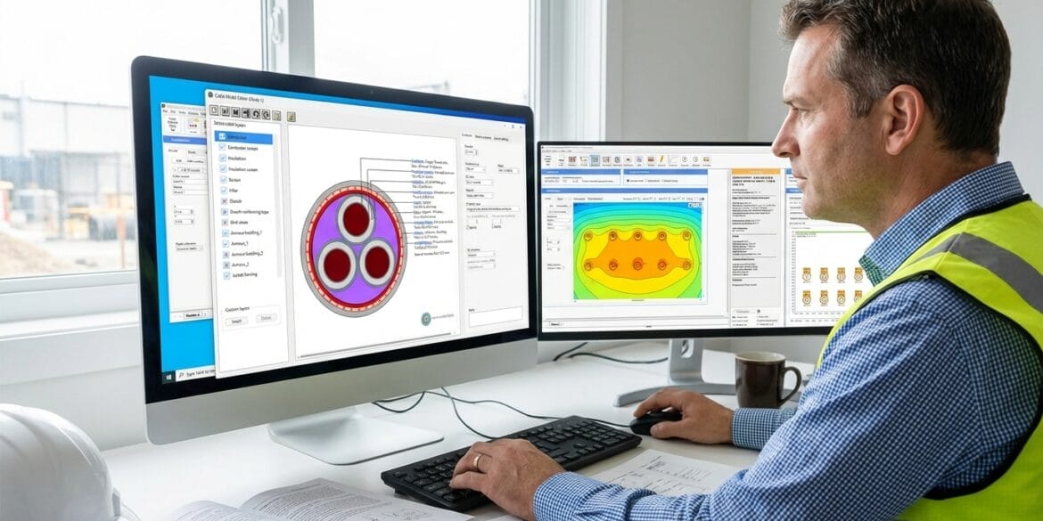
ELEK Cable HV Software has been used for the modelling.
This article includes several case study calculations and technical theory.
How Multiple Circuits in One Duct Affect Current Ratings
When multiple circuits are housed inside the same duct, the number of bundled circuits and their arrangement can significantly affect the current rating. No standards provide derating factor tables for dealing with multiple circuits in a duct. We have performed accurate finite element modelling.
Number of Circuits in a Duct
Figure 1 below shows how increasing the number of circuits affects the current rating.

The filling factor of cables in a duct represents the percentage of the duct’s internal cross-sectional area occupied by cables. The standards impose maximum fill factor limits for conduits, not primarily for ampacity reasons but to ensure cables pulled into ducts are not damaged.
Here are the critical observations from the plot:
Ampacity decreases as circuits increase.
As more circuits are installed in the same duct, the current-carrying capacity per circuit reduces because of increased mutual heating.Greatest derating occurs at low-to-moderate fill.
The most severe reduction in current rating happens when moving from a relatively empty to a moderately filled duct. After this point, the decline continues but at a slower rate.Thermal crowding effects.
At higher filling levels, thermal crowding is the dominant factor in ampacity reduction, as reduced air circulation and closer cable proximity intensify mutual heating.
Arrangement of Circuits in a Duct
The arrangement of the cables is another essential factor affecting the current rating of multiple circuits inside a duct. Various arrangements can influence the temperature of the duct filler, leading to significant changes in the current rating. Figure 2 below shows how multiple arrangements affect the current rating of the circuit.

Here are the critical observations from the plot:
Arrangement influences ampacity.
The way circuits are positioned inside the duct directly affects their current-carrying capacity.Best performance with distributed spacing.
When circuits are reasonably spaced throughout the duct (Arrangement A), heat dissipation is maximised, and the ampacity per circuit is highest.Proximity leads to significant derating.
Whenever circuits are bunched together inside the duct — whether crowded in the centre (Arrangement B) or cradled at the bottom (Arrangement C) — the mutual heating effect is more substantial and the ampacity drops. Arrangement C, where cables rest at the bottom of a duct, is the most common practical case in real installations.
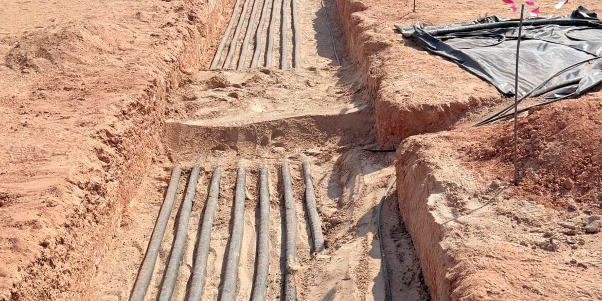
Case Study - 12 x DC Circuits in Ducts
The installation involves 12 DC circuits arranged in four ducts. The positive polarities of the first six circuits are in the first duct, and the negative polarities are in the second duct. The third and fourth ducts house the positive and negative polarities of the remaining six circuits. The cable used in this case study is a 1.5 kV, 240 mm² copper DC solar sub-array cable. The cables are installed in high-density polyethylene (HDPE) ducts. The ducts are arranged in a flat formation surrounded by native soil. Since solar cables operate under DC conditions, sheath/screen current losses are negligible. The detailed parameters are listed as follows:
| Parameter | Value | Units |
|---|---|---|
| Depth (from ground surface to centre of ducts) | 0.6 | m |
| Duct outer diameter (Do) | 160 | mm |
| Duct thickness | 5 | mm |
| Axial distance among ducts | 0.3/0.6/0.3 | m |
| Maximum operating conductor temperature | 90 | °C |
| Ambient ground temperature | 15 | °C |
| Ambient air temperature (for non-isothermal ground surface conditions) | 25 | °C |
| Soil thermal resistivity | 1.2 | K.m/W |
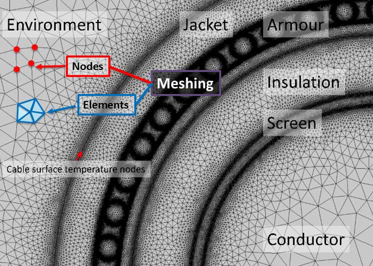
Mesh Generation
The initial step of FEM analysis is discretising the space into smaller elements called meshes. In FEM, a mesh is the division of the model geometry into many small 2D triangles. Figure 1 shows the mesh plot for the buried conduits with solar cables, and Figure 4 shows the zoomed-in mesh plot for one conduit with the enclosed solar cables.


Results
Case 1: Steady-State Current Rating, Assuming Isothermal Ground Surface (Ideal) Conditions
Case 1 evaluates the cable current rating using a conventional approach, assuming an isothermal ground surface and a constant load current of 242.62 A. The cables carry equal (balanced) load currents, as the connected PV panels produce uniform power output under identical environmental conditions (partial solar shading of the solar panels has been ignored).
Figure 5 presents the calculation results, and Figure 6 shows the temperature distribution.


The current-carrying capacity for each circuit is 242.62 A (rounded down to 240 A).
The rating is limited by the hottest cable at the system’s centre, which is experiencing the most mutual heating.
Cables at the perimeters remain relatively cooler, with conductor temperatures below the maximum operating temperature.
Case 2: Steady-State Current Rating, Assuming Non-Isothermal Ground Surface Conditions
For cables buried close to the ground surface, assuming an isothermal ground can overestimate their ampacity. The temperature at the soil-air interface is influenced by the heat generated by the cables and the air temperature above the soil. Therefore, in Case 2, the cable current rating is recalculated using a non-isothermal ground surface assumption, and the air temperature is 25°C. The ground temperature distribution is estimated based on convective heat transfer at the ground–air interface.
The resulting cable sizing outcomes are shown below:

The corresponding temperature distribution is illustrated in the figure below:

-
The current-carrying capacity for each circuit is 208.13 A (rounded down to 205 A).
-
The rating is relatively lower compared with case 1. However, this calculation considers practical thermal conditions at the ground surface, which helps avoid system thermal runaway.
-
With practical consideration of the non-isothermal ground surface, the soil is getting hotter overall, reducing the cable system’s ampacity.
Case 3: Cyclic Rating, Assuming Non-Isothermal Ground Surface Conditions
As previously mentioned, the power output from PV panels varies periodically with solar irradiance. This means the cable rarely operates at its maximum current, and the load typically drops to zero during nighttime. Therefore, Case 3 evaluates the cable’s current-carrying capacity under a cyclic load condition.
According to IEC 60853 [3], applying a cyclic rating factor M to the steady-state rating can determine the cyclic current rating. The value of M is derived from the load profile of the solar PV system, as illustrated below:

The load profile reflects daily solar variation with a peak at noon and zero at night (Figure 9).
Despite non-isothermal ground surface conditions, IEC 60853 cyclic loading factors show that cables can carry significantly more current than steady-state ratings.
Utilising the cyclic loading pattern for solar PV farms avoids unnecessarily oversizing cables.
Key Engineering Takeaways
It’s practically convenient to combine multiple cable circuits inside the same duct.
The greater the number of cables inside the same duct and parallel ducts in the same trench, the greater the mutual heating between them.
Calculating the current rating of multiple circuits in the same duct requires the finite element method because the standard IEC 60287 equations do not address these conditions.
The cable circuits’ non-continuous loading should be considered, as this significantly increases their current-carrying capacity.
Proper modelling of ground surface conditions, including the effects of air temperature and convection with the ground surface, results in more accurate current rating results.
Current Rating Theory for Multiple Circuits in Shared Ducts
Solar cables in a PV system are designed to transfer power from the solar modules to the inverter. Incorrect installation affects their functionality, directly impacting the PV system’s performance.
The cable’s ampacity highly depends on thermal conditions, which are primarily decided by the cable’s installation environment. Direct burial of solar cables is an easy and cost-effective solution, but direct burial runs the risk of damage from environmental hazards. Compared with the direct burial conduit installation, it has the following benefits:
Environmental Protection: Conduits shield cables from moisture, heat, and corrosion, extending their service life.
Electrical Safety: Properly installed conduit reduces the risk of short circuits, electrical shocks, and fire hazards.
Wiring Management: Conduits help organise and route cables neatly, making maintenance and troubleshooting easier.
Thermal Analysis
To estimate the current rating of the cables installed in an air-filled duct/casing, the most essential task is to quantify the heat transfer rate between the cable surface and the air inside the duct. Compared with the single-circuit-in-duct scenario, where the air flow inside the duct is relatively simple and well-modelled by many empirical equations, the air flow when multiple circuits are in a duct can be complex and cannot be analysed by empirical equations. Based on the experimental tests and FEM analysis, the thermal model can be built following the guidelines below:
-
The heat dissipation outside the conduit is via soil conduction.
-
The heat dissipation inside the conduit (empty) is via air convection.
-
The heated air inside the duct rises along the surface of the cable.
-
The airflow is confined within the duct and circulates by descending along the cooler duct wall.
-
This creates a symmetrical circulating airflow pattern, as shown in Figure 10.

Electrical Analysis
Steady-State Current Rating
The current rating for cables connected to solar PVs can differ from that of traditional underground cables. From the electrical perspective, solar cables are usually low-voltage DC cables, which do not have screen/sheath losses like AC cables. The dielectric losses and electrical stress concerns can also be ignored for cables operated in a low-voltage range.
The IEC 60287 [1] series provides the general steady-state thermal calculation for cable current rating.
\(I=\left[\frac{\Delta\theta-W_{\mathrm{d}}\left[0.5T_1+n\left(T_2+T_3+T_4\right)\right]}{R_{\mathrm{C}}T_1+nR_{\mathrm{C}}\left(1+\lambda_1\right)T_2+nR_{\mathrm{C}}\left(1+\lambda_1+\lambda_2\right)\left(T_3+T_4\right)}\right]^{0.5}
\)
Δθ is the conductor temperature rise above the ambient temperature (K);
T1 is the thermal resistance per unit length between one conductor and the sheath (K.m/W);
T2 is the thermal resistance per unit length of the bedding between sheath and armour (K.m/W);
Т3 is the thermal resistance per unit length of the external serving of the cable (K.m/W);
Т4 is the thermal resistance per unit length of the space between the cable surface and the surrounding medium(e.g. soil);
Rc is the alternating current resistance per unit length of the cable at maximum operating temperature (Ω/m);
n is the number of load-carrying conductors in the cable (conductors of equal size and carrying the same load);
Wd is the dielectric loss per unit length of the cable for the insulation surrounding the conductor (W/m);
λ1 is the ratio of losses in the metal sheath to total losses in all conductors in that cable ;
λ2 is the ratio of losses in the armouring to total losses in all conductors in that cable.
Cyclic Rating
In addition to the steady-state current rating, the cyclic load condition should also be considered for solar PV cables, as the power generated by the PV farms is proportional to the solar irradiance, which can be seasonal. The characteristics of a load from a PV system are given as follows:
-
The power generated from the connected PV panels decides the load the solar cable connected to the PV system carries.
-
Figure 9 [3] below shows a typical per-unit photovoltaic power for a sunny day.
-
The power will become maximal at midday when the sunshine is strong and turn to zero after sunset.
-
This means the load carried by the solar cables is not constant, where a cyclic rating guided by the IEC 60853 [4] can be applied for a higher system rating.

Conclusions and Recommendations
This article presents a method for calculating the current rating when multiple circuits are bundled inside a duct. It studies a real-world solar cable installation to highlight the importance of considering practical conditions for accurate ampacity assessment. Unlike conventional AC cables, DC solar cables do not experience sheath/screen losses. Installation conditions and the fluctuating solar generation output mainly determine their current-carrying capacity.
Several case studies were performed using the FEM installation and Transient module in ELEK Cable HV Software to compare different assumptions related to ground temperature and load profile. A more realistic and optimised current rating can be achieved by considering both non-isothermal ground conditions and cyclic loading. This approach ensures safe cable operation while avoiding excessive heating and oversizing, which can reduce material costs and improve installation efficiency.
References
[1] IEC 60287: Electric cables – Calculation of the current rating – Part 1: Current rating equations (100% load factor) and calculation of losses.
[2] IEC 62930: Electric cables – Cross-linked polyethylene insulated cables for photovoltaic systems.
[3] IEC 60853: Calculation of the cyclic and emergency current rating of cables – Part 1: Cyclic rating factor for cables up to and including 18/30 (36) kV.
[5] AS/NZS 2053: Conduits and fittings for electrical installations.
[6] AS/NZS 4130: Polyethylene (PE) pipes for pressure applications.
[7] AS/NZS 5000: Electric cables – Polymeric insulated – For working voltages up to and including 0.6/1 (1.2) kV.