Table of Contents
Overview
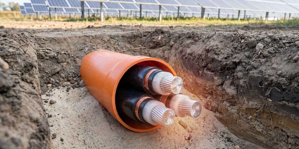
This report explains how to perform accurate ampacity calculations for popular low-voltage (LV) industrial power cables and medium-voltage (MV) utility power cables from Southwire. The term “ampacity” has the same meaning as “current rating.”
Southwire Company, LLC, commonly known as Southwire, is one of North America’s leading manufacturers of wire and cable solutions. They supply a wide range of products, including overhead conductors, utility power cables, metal-clad power cables, building electrical wires, industrial power cables, and more.
The cable datasheets included standard ampacity ratings for generic cables for fixed conditions, taken from simple lookup tables by Southwire directly from ICEA P-117-734-2016 [ref. 1].
![]()
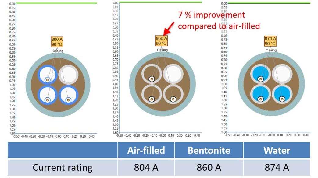
Ampacity ratings taken directly from standards are not accurate. These ratings do not consider the actual construction of your cables or the actual installation conditions.
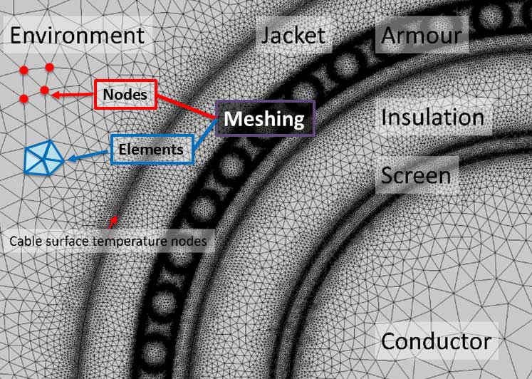
We modelled hundreds of these cables using the actual cable construction from the manufacturer’s (Southwire) datasheets. We used ELEK Cable HV Software, based on IEC 60287 [ref. 2] and CIGRE TB 880 [ref. 3], to perform the accurate ampacity calculations.
The software’s ampacity values matched those listed on the datasheets for the standard (fixed) installation conditions. Three (3) case studies are included below.
Standards considered for ampacity calculations
The following standards were considered for the ampacity calculations and comparison of the results. The calculation methods therein are considered accurate due to their detailed thermal modeling, empirical validation, standardization processes, correlation with field data, and continuous improvements. Their methodologies ensure safe and efficient design and operation of electrical cable systems under various operating conditions.
IEC Standard 60287
IEC 60287 is a set of international standards developed by the International Electrotechnical Commission (IEC) for the calculation of the current-carrying capacity (ampacity) of electric cables. The standard uses a thermal equivalent circuit model of the cable and installation environment to determine an ampacity that does not exceed the temperature limits of the cables. This standard provides a widely accepted method, to which many engineers and scientists have contributed in the past, and will contribute to in the future. Note there are situations where the calculations recommended by IEC are not fully correct, therefore the guidance points of CIGRE Technical Brochure 880 [ref. 3] should be applied to the IEC-based calculations.
Neher-McGrath method
ANSI/ICEA Standards
ANSI/ICEA standards refer to the standards developed jointly by the American National Standards Institute (ANSI) and the Insulated Cable Engineers Association (ICEA). This standard provides specific guidelines for cable construction, materials and performance requirements. This standard also provides procedures for testing cables to verify compliance with the specified requirements and recommendations the proper installation, handling, and maintenance of cables to ensure safe and reliable operation throughout their service life.
Cable modelling
The cables from Southwire were modelled by taking information from cable datasheet and ICEA standards. Information about the material, construction and diameter/thickness of the layers of the cables were taken from the datasheets while the ICEA standards provided information on installation conditions (this is because their were notes on the datasheet that their quoted ampacities were based on ICEA ratings).
Although the datasheet contained most of the important parameters to model the cables such as diameter over the conductor, diameter over the insulation, outer diameter of the cable etc., not all the parameters are given. In these cases, we made logical assumptions.
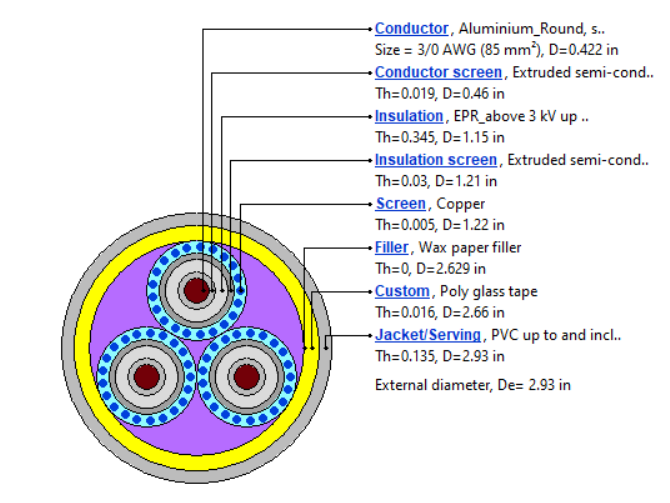
The specifications and general assumptions about each layer type is listed as follows:
General settings: All cables types are extruded and three phase. The supply frequency was set to 60 Hz. Voltage and number of cores are changed according to the specifications in the datasheet.
Conductor: Conductor size, diameter and material were directly taken from the datasheet. Class 2 stranded conductors were used to model all the conductors. Sizes ranged from 1/0 AWG to 2000 Kcmil.
Conductor screen: The diameter and thickness of the conductor screen were not available in the datasheet. Taking the insulation diameter and subtracting the thickness of the insulation from its diameter gave us the diameter of the conductor screen.
Insulation: The diameter, thickness and maximum operating temperature of the insulation was available. Insulation type was set to either XLPE or EPR depending on the manufacturer specifications. Insulation properties such as relative permittivity, thermal resistivity, specific heat capacity and maximum short-circuit temperature are automatically set in the software depending on the insulation type.
Insulation screen: Diameter of insulation screen was available. Setting the diameter of the insulation screen in the software will automatically set the thickness. Material is always set to extruded semi-conductor type.
Screen/Tape shield: From the manufacturer datasheet, we know that copper tape with 25% overlapping is used for screen with a thickness of 0.005 inches. For single core cables, number of wire and thickness of screen was available.
Grounding conductor: Grounding conductor was excluded from the model in the software.
Filler: A custom material type was always used. Thickness was set as 0, and to match the datasheet, maximum short circuit temperature was set to 250o C.
Binder: Binder diameter and thickness was calculated from jacket diameter and thickness similar to conductor screen. From the datasheet, maximum short circuit temperature = 250o C.
Jacket: Jacket thickness and diameter was provided in the datasheet. Depending on what was specified, PVC or polyethylene was used for the jacket material.
Ampacity calculations
The cables were modelled in the software using the cable model datasheet provided by Southwire and verified using the ampacity value provided on the manufacturer datasheet. The ampacity values on the datasheet were directly taken from the ANSI/ICEA P-117-734 standard [ref. 1].
The ampacity calculations in that standard were performed with the software program CYMCAP version 5.3 Rev 2. The methodology used to the the calculations in CYMCAP is based on Neher-McGrath and IEC 60287.
![]()
The 2016 version of the ANSI/ICEA P-117-734 predates the release of CIGRE TB 880 (2023). Therefore the ampacity values in the standard (provided by CYMCAP software) are not accurate because they were not calculated using best practices.
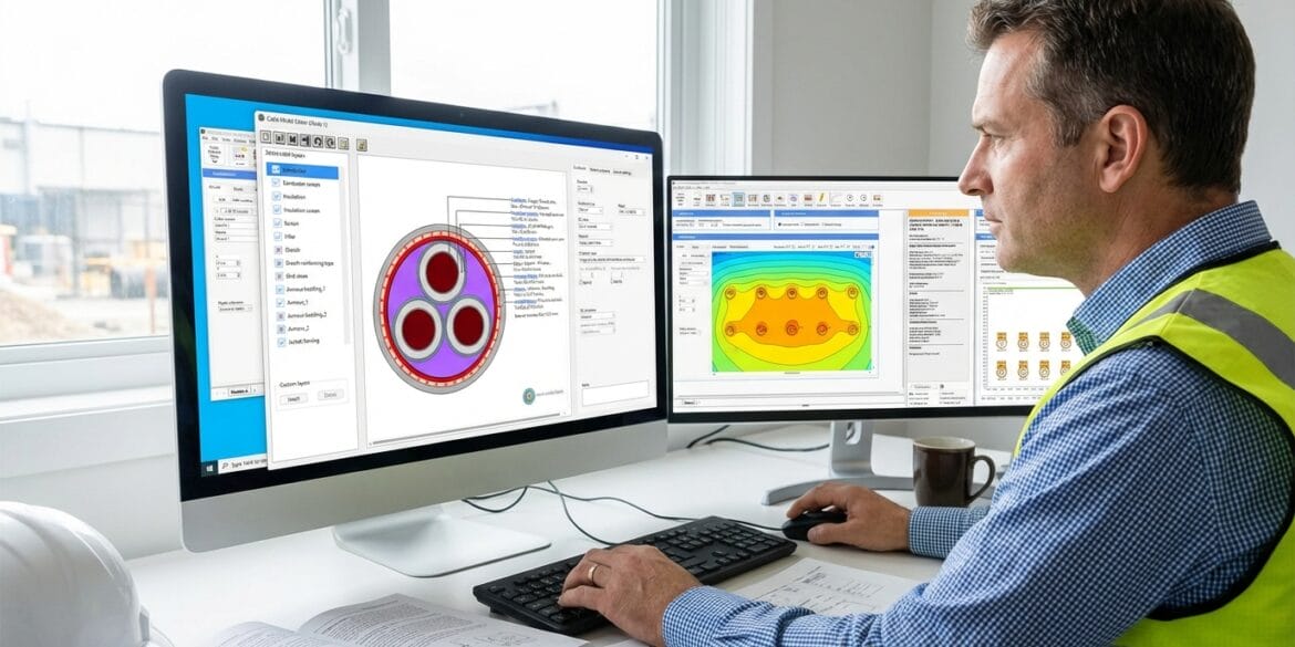
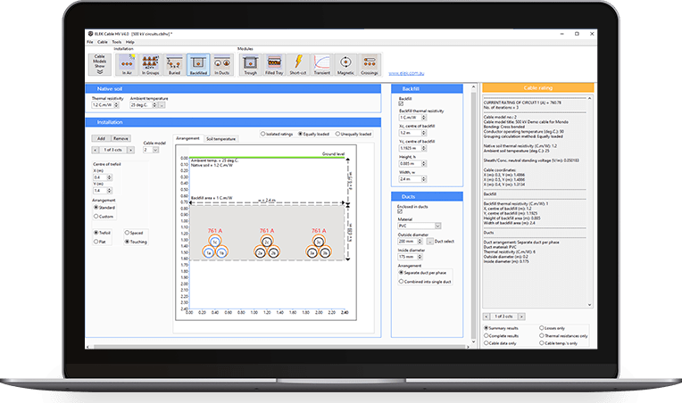
The ampacity calculations provided by ELEK Cable HV Software are also based on Neher-McGrath and IEC 60287. Furthermore, the software is updated to match with CIGRE Technical Brochure 880 [ref. 3].
We modelled the cables in the software as accurately as possible with the information that was provided. We roughly validated the model by comparing our calculated ampacity with that on the datasheet which was taken from the ICEAP standards.
Standard conditions
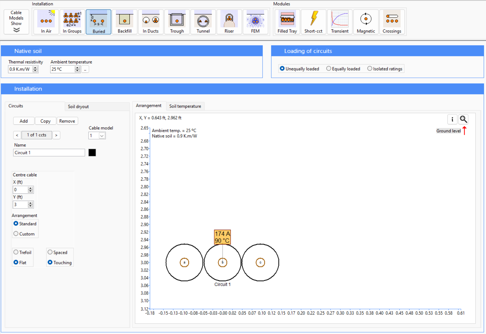
Installation conditions and ampacity calculations of Southwire cables are based on ICEA P-117-734-2016 standard [ref. 1]. The standards for the installations are provided below:
Thermal resistivity = 0.9 K.m/W. [ICEA, Section: 3.1.4]
Maximum conductor temperature = 90o C and 105o C for 15 and 35 kV cables. [ICEA, Section: 3.1.5]
Ambient earth temperature for direct buried cables = 25o C [ICEA, Section: 3.1.5]
Burial depth = 36 inches (3 feet). [ICEA, Section: 3.1.12]
Duct configuration: [NFPA70, Section: 315.60, 350.60]
Ambient earth temperature = 20o C
Thermal resistivity = 0.9 K.m/W.
Material = PVC
Burial depth = 36 inches (3 feet)
Installation condition for single circuit directly buried = Flat/touching [ICEA, Figure.3, Section.7]
Installation condition for single circuit buried in duct = Trefoil/touching [ICEA, Figure.7, Section.7]

Results
Utility and industrial cables are modelled from Southwire cable library. The construction depends on the type of use. Some of the notable cables and calculation results are discussed below.
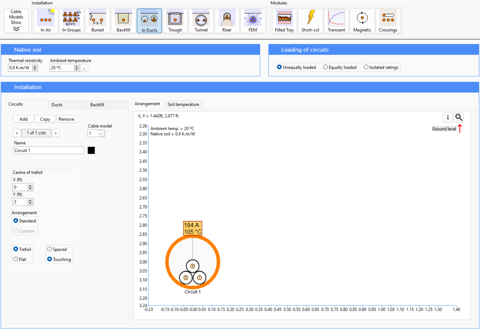
Cable type 1 - 25 kV AL 100% TRXLPE Full Neutral LLDPE
Description: Single Conductor, 260 Mils Tree Retardant Cross Linked Polyethylene, 100% Insulation Level, Full Concentric Neutral, Linear Low Density Polyethylene (LLDPE) Jacket. Silicone Free
Datasheet: SPEC 81141
| Voltage (kV) | Number of conductors | Number of phases | Frequency (Hz) |  |
|---|---|---|---|---|
| 25 | 1 | 3 | 60 |
Installation conditions:
Assumptions:
-
Conductor screen and diameter calculated from insulation thickness and diameter.
-
Conductor screen diameter calculated from insulation diameter and thickness.
-
Insulation screen thickness calculated from insulation screen diameter.
-
Screen thickness and diameter calculated from jacket thickness and diameter.
-
Lay length factor of screen assumed to be 1.05.
Findings:
The ampacities in ELEK Cable HV Software closely matches which ICEAP. The largest difference is 2.74% for 1 (Solid) AWG conductor and the closest matching is for 4/0 AWG conductor with a difference of 0.76%. For all the cases, ELEK Cable HV Software has a slightly higher rating than ICEAP.
| Conductor size (AWG/Kcmil) | Ampacity in ICEAP (A) | Ampacity in ELEK Cable HV Software (A) | Difference ( % ) |
|---|---|---|---|
| 1 (Solid) | 170 | 174.79 | 2.74 |
| 1 | 170 | 175.04 | 2.88 |
| 1/0 (Solid) | 195 | 198.22 | 1.62 |
| 1/0 | 195 | 197.85 | 1.44 |
| 2/0 | 220 | 224.79 | 2.13 |
| 3/0 | 250 | 253.73 | 1.47 |
| 4/0 | 285 | 287.18 | 0.76 |
| 250 | 307 | 313.42 | 2.05 |
| 350 | 365 | 370.13 | 1.39 |
Cable type 2 - CU Compressed 8 kV NLEPR Insulation 133% IL SIM-PVC Jacket. MV 105 - Tray Rated - Sunlight Resistant
Description: Type MV-105 Single Conductor Copper, 140 Mils No Lead Ethylene Propylene Rubber (NL-EPR) 133% Insulation Level, Tape Shield, SIMpull Polyvinyl Chloride (PVC) Jacket, Dual Rated UL/CSA
Datasheet: SPEC 46271
| Voltage (kV) | Number of conductors | Number of phases | Frequency (Hz) |  |
|---|---|---|---|---|
| 8 | 1 | 3 | 60 |
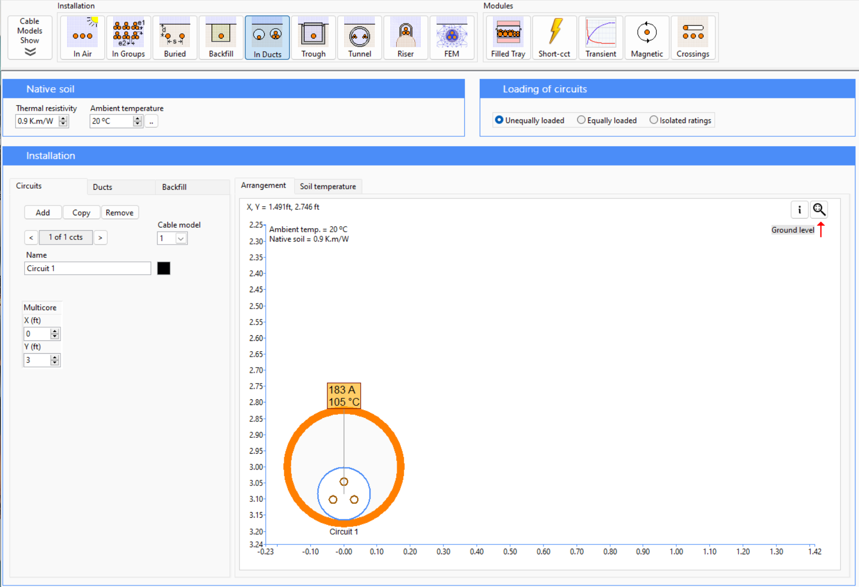
Installation conditions:
![]()
For industrial products, Southwire follows NFPA70-2023 [4] standards for installation in ducts. The only notable difference is that the ambient air temperature in ducts is set to 20o C.
Assumptions:
Duct diameters was not provided. Diameter was assumed to match the current ratings.
Conductor screen diameter calculated from insulation diameter and thickness.
Insulation screen thickness calculated from insulation screen diameter.
Lay length factor of screen specified to be 1.01.
Tape width of screen assumed to be 2 inches.
Number of tape assumed to be 2.
Lay length factor of screen assumed to be 1.05.
Findings:
The ampacity in ICEAP is slightly higher than ELEK Cable HV Software. Exception can be seen for 750 Kcmil and 1000 Kcmil conductors where the ampacity in ELEK Cable HV Software is higher than ICEAP. Answers match closely with an average difference of 1.4%.
| Conductor size (AWG/Kcmil) | Ampacity in ICEAP (A) | Ampacity in ELEK Cable HV Software (A) | Difference ( % ) |
|---|---|---|---|
| 2 | 165 | 162.50 | 1.52 |
| 1 | 185 | 184.46 | 0.29 |
| 1/0 | 215 | 209.91 | 2.37 |
| 2/0 | 245 | 238.59 | 2.61 |
| 3/0 | 275 | 271.42 | 1.30 |
| 4/0 | 315 | 312.13 | 0.91 |
| 250 | 345 | 341.72 | 0.95 |
| 350 | 415 | 410.26 | 1.14 |
| 500 | 500 | 498.01 | 0.40 |
| 750 | 610 | 612.71 | -0.44 |
| 1000 | 690 | 696.24 | -0.90 |
Cable type 3 - CU Compressed 15 kV NLEPR Insulation 100% IL Black PVC Jacket. MV 105 - Tray Rated - Sunlight Resistant
Description: Type MV-105 Three Conductor Copper, 175 Mils No Lead Ethylene Propylene Rubber (NL-EPR) 100% Insulation Level, Tape Shield, Polyvinyl Chloride (PVC) Jacket, Dual Rated UL/CSA. Silicone Free
Datasheet: SPEC 46401
| Voltage (kV) | Number of conductors | Number of phases | Frequency (Hz) |  |
|---|---|---|---|---|
| 15 | 3 | 3 | 60 |
Assumptions:
Duct diameters was not provided. Diameter was assumed to match the current ratings.
Lay length factor specified to be 1.01.
Conductor screen diameter calculated from insulation diameter and thickness.
Insulation screen thickness calculated from insulation screen diameter.
Tape width of screen assumed to be 2 inches.
Lay length factor assumed to be 1.01.
For Filler, the Thermal Resistivity was kept at 5 K.m/W as the average Thermal Resistivity of paper fillers are 5 K.m/W.
Custom layer used for Binder with custom material. Thermal resistivity of poly glass tape is 2.5 K.m/W.
Diameter of binder calculated from diameter and thickness of Jacket.
Jacket lay length factor was specified to 1.01.
Findings:
The modelling of this cable is very accurate as the average difference in ampacity is 0.8%, where the closest matching cable has a difference of 0.05% and the highest difference is 1.65%. In all the cases, the rating of ICEAP is slightly higher.
| Conductor size (AWG/Kcmil) | Ampacity in ICEAP (A) | Ampacity in ELEK Cable HV Software (A) | Difference ( % ) |
|---|---|---|---|
| 2 | 160 | 159.92 | 0.05 |
| 1 | 185 | 183.78 | 0.66 |
| 1/0 | 210 | 208.91 | 0.52 |
| 2/0 | 235 | 231.12 | 1.65 |
| 3/0 | 270 | 265.70 | 1.59 |
| 4/0 | 305 | 302.06 | 0.97 |
| 250 | 335 | 330.53 | 1.33 |
| 350 | 400 | 397.99 | 0.50 |
| 500 | 485 | 479.71 | 1.09 |
| 750 | 585 | 582.58 | 0.41 |
Conclusions
The ampacity of cables manufactured by Southwire has been calculated using ELEK Cable HV Software. Firstly the cables were modelled based on the properties provided on the datasheets. The manufacturer datasheets also included a set of ampacity values for standard installation conditions. These were taken from the ICEAP standards, that were based on a standard (fixed) set of installation conditions using IEC 60287 and the Neher-McGrath calculation methods.
The ampacity values on the cable datasheets were used to validate that the cables had been modelled correctly. The ampacity ratings calculated using ELEK Cable HV Software were close to those on the datasheets, indeed verifying that the modelling had indeed been done correctly.
![]()
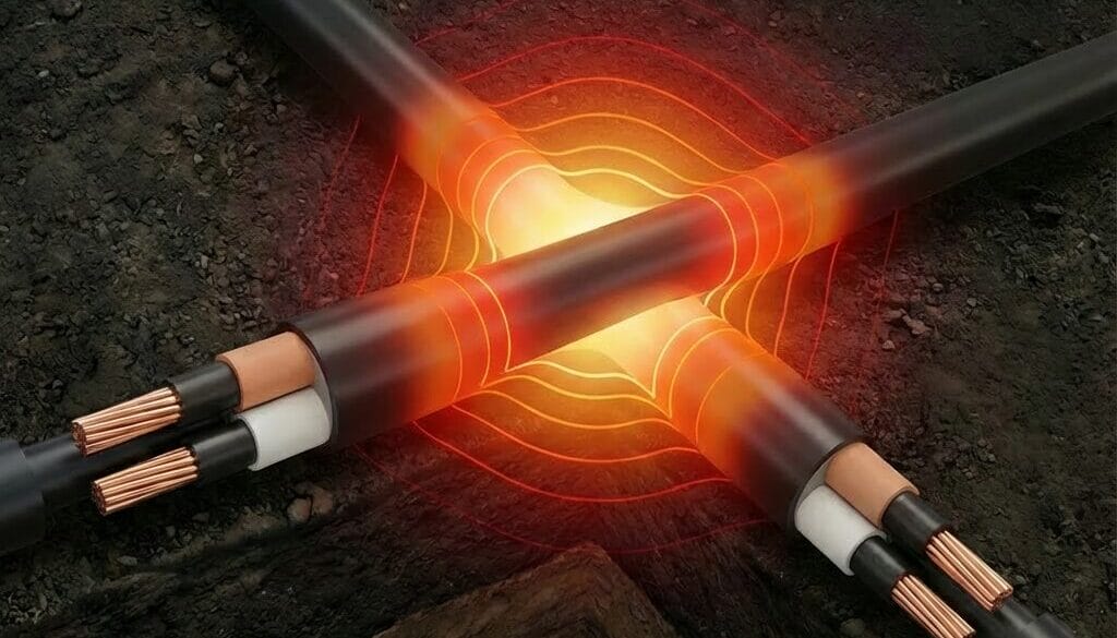
Less than a 3 % difference between the ampacity given by the software models and the datasheets across all cable types was achieved.
However, the ampacity ratings given by ELEK Cable HV Software should be regarded as being more accurate than those given on the datasheet. The major benefit of the modelling is the software can provide accurate ampacity results for non-standard installation conditions.
References:
[1] ANSI/ICEA P-117-734-2016, “Ampacities For Single-Conductor Solid Dielectric Power Cable 15 kV Through 35 kV,“
[2] IEC 60287:2023 SER Series. Electric cables – Calculation of the current rating.
[3] CIGRE B1 Insulated Cables Technical Brochure. “Power cable rating examples for calculation tool verification.” Reference 880. September 2022
[4] NFPA70-2023.“National Electrical Code,”
[5] POLYPRES S.A., “POLYGLASS: Polyethylene in Ultra-High Molecular Weight (UHMW-PE),” Alfarrasí, Valencia, Spain.
[6] Neher, J. H.; McGrath, M. H. (October 1957). “The Calculation of the Temperature Rise and Load Capability of Cable Systems”.
[7] ELEK Cable HV Software, V6.5.