0

Your Cart

0
Subtotal: AUD0
No products in the cart.
Home / Tutorials / PDF Underlay Tool Tutorial

PDF Underlay Tool Tutorial

SafeGrid Earthing Version 6.2

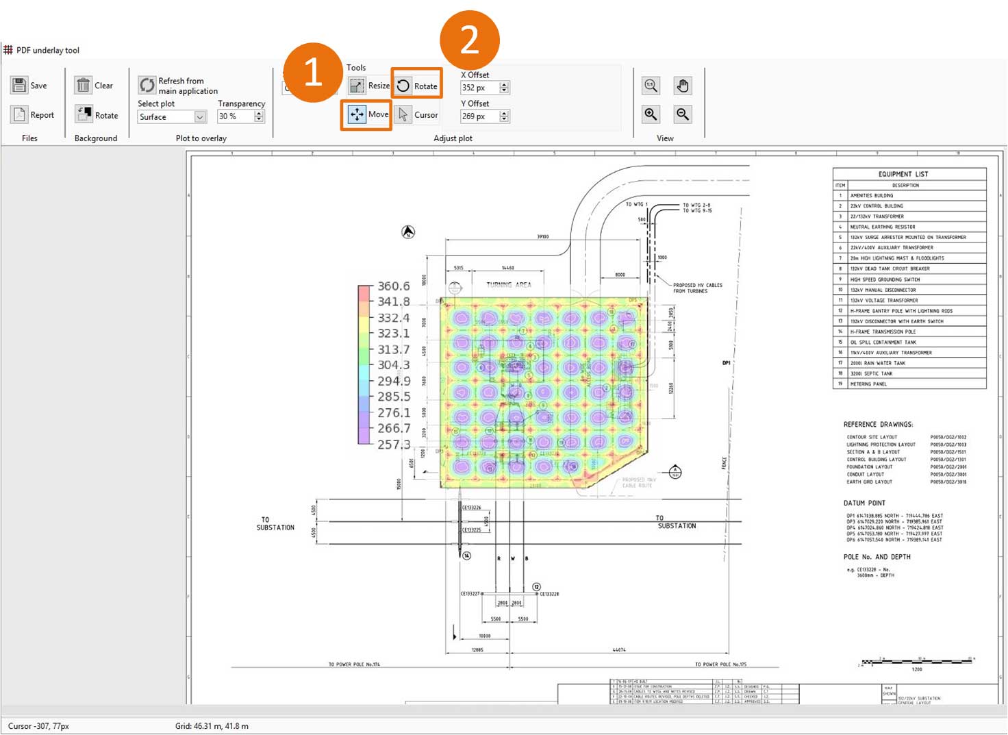
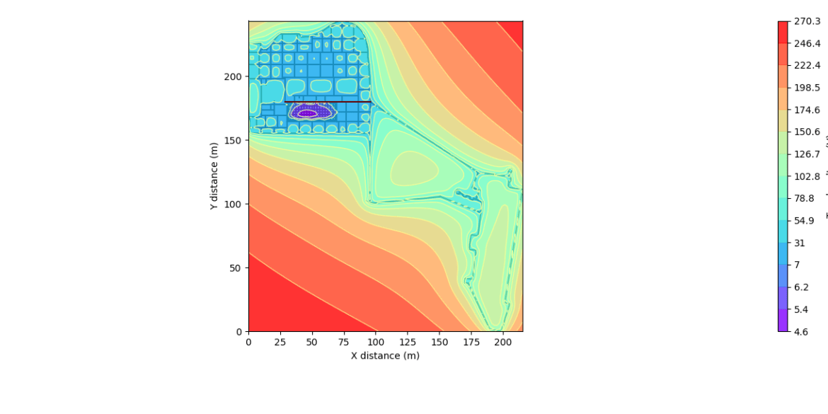
The PDF underlay tool is an addon to the Display Results module of SafeGrid.  This tool allows you to overlay the surface, touch or step voltage plots on your site drawings.

The process is simple.  Import your PDF or image file as a background.  Resize the plots to match the scale of the background then move the plots to align with the objects on your drawing.

The following steps will show you how.

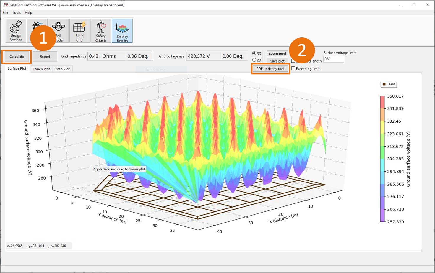
1. Calculate the voltage plots

The number one in a yellow circle representing renewables.

Click Calculate in Display Results to calculate the surface, step, touch voltage plots.

A yellow circle with the number two representing renewable power.

Click PDF underlay tool to open the tool.

2. Load a PDF drawing file

Import a background drawing or image by dragging and dropping the file into the tool or selecting it from disk.  For multipage PDF documents you can select the correct page.

You can rotate the background drawing using the Rotate button.

3. Scale the plot

The plot needs to be scaled to match the dimensions of the background drawing.

The number one in a yellow circle representing renewables.

Select the Plot from the Selection

A yellow circle with the number two representing renewable power.

Click the Resize tool button.

The yellow circle represents the number 3 in an electrical world.

Click the Measure scale on background button and use the mouse to draw a line on the background drawing then specify its corresponding length same as it is set in the original drawing to automatically scale the plot.

4. Move the plot into position

The number one in a yellow circle representing renewables.

Move the plot to its position by pressing the Move button and using the mouse.

A yellow circle with the number two representing renewable power.

Use the Rotate tool button and the mouse to rotate the plot into position as required.

Use the mouse scroll wheel to zoom and the other View controls for easy viewing.

Change the plot using the Select plot under Plot to overlay on the control bar.

5. Move and scale the colour bar

The number one in a yellow circle representing renewables.

Select the Colour Bar from the Selection dropdown.

A yellow circle with the number two representing renewable power.

Move the Colour Bar into position by pressing the Move button and using the mouse.

The yellow circle represents the number 3 in an electrical world.

Click the Resize tool button and scale the Colour Bar by adjusting the Height or Width values.

6. Create a report

Click Report to create a new PDF of the combined background and the plot.

Alternatively, click Save to store as an image file.
Related Tutorials:

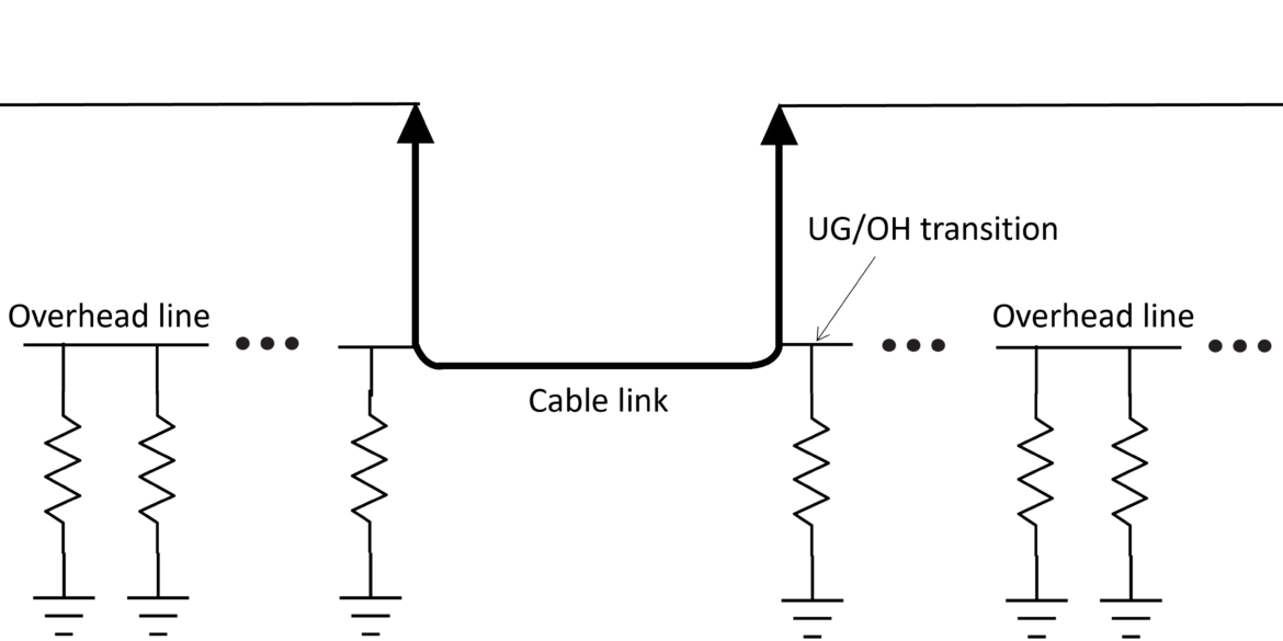
This tutorial shows how to use the Fault Current Distribution module in ELEK SafeGrid Earthing Software to model an earth fault on an overhead transmission line with an underground cable link.
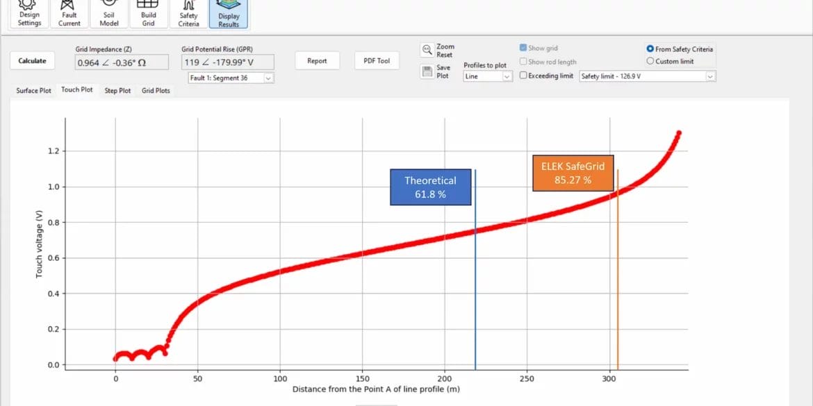
With the Fall of Potential Test, the resistance of an earthing system is measured using a remote earth electrode. There is a theoretical position of 61.8 % of the separation distance between the measured grid and the remote electrode, which is the correct position for measuring the exact grid impedance for uniform soil resistivity but not for multilayer soils. This tutorial shows ELEK SafeGrid Earthing Software users how to simulate an FOP test.
This video tutorial focuses on the design and modelling of Earthing Systems for Wind Farms and Solar PV Farms. Real-world examples are provided and are explained.
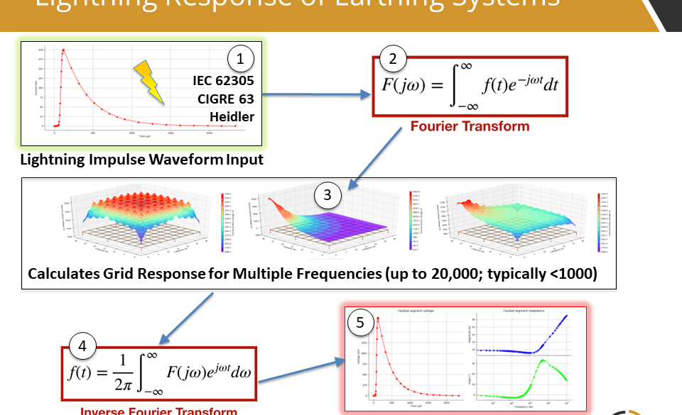
ELEK SafeGrid Earthing Software can perform calculations in the time domain such as for lightning currents. Transient waveforms are composed of many frequency components and Fourier transforms are used. The transient waveform types include IEC 62305, CIGRE, Heidler, Double-exponential, and Custom. The time-domain response of an earthing system can be analysed.
SafeGrid can model custom earthing arrangements of any size or shape in 2D or 3D. You can specify the grid using the in-built editor tools or you can import grids drawn in AutoCAD.
This video (25 min) tutorial shows the main features of SafeGrid Earthing Software for performing an earthing designs and explains the design process.