0

Your Cart

0
Subtotal: AUD0
No products in the cart.
Home / Tutorials / Load Grid from DXF AutoCAD File

Load Grid from DXF AutoCAD File

ELEK SafeGrid Earthing Version 7.0

Table of Contents

Introduction

ELEK SafeGrid Earthing Software can model custom earthing arrangements of any size or shape in 2D or 3D.You can specify the grid using the in-built editor tools or you can import grids drawn in AutoCAD.
It is easy to draw grids in AutoCAD as connected entities, then save them in the DXF file format and to import them into SafeGrid for calculations. This tutorial will show you how.

The advantages of importing grids from AutoCAD include:

  1. a) Earthing design drawings created in AutoCAD can be imported directly without re-drawing. This saves time and ensures an accurate representation of the grid.
  2. b) Custom and complex grids that may be difficult to create with the in-built grid editor can be analysed.
  3. c) Buried conductor arrangements drawn in 3 dimensions (3D) – X, Y, Z coordinates system can be modelled.

1. Rules for importing

The rules of drawing grids in AutoCAD include:
  • a) Earthing system drawing should be saved as an ASCII DXF file.
  • b) Set the measurement units of the AutoCAD drawing to be in Meters, Centimetres, Millimetres, Inches, or Feet.
  • c) Draw the grid using only Lines, Polylines, LWPolylines, Circles, or Arcs entities.
  • d) Circles and Arcs will be converted to Lines when imported.
  • e) Lines snap connected otherwise an undesired current discontinuity will occur.
  • f) If drawn in 3D, Positive (+’ve) Z coordinate signifies depth and negative (-’ve) Z coordinate signifies above-ground.

2. Drawing the earthing system in AutoCAD

Draw your earthing system in AutoCAD (or equivalent software) as connected straight lines, polylines, circles, or arcs.

You can add to an existing drawing, just make sure to create a unique and independent drawing layer or layer(s) for each uniqueearthing system. For example, the earthing system in Figure 1are within unique layers.

Figure 1 – Earthing system are within unique layers in AutoCAD
Set the drawing units in AutoCAD using the UNITS command otherwise if they are not set in the drawing then they can be specified while importing the drawing into SafeGrid.
Figure 2 – Setting the Drawing Units in AutoCAD
Once the earthing system drawing is completed and ready to be imported then save the drawing as ASCII DXF (.dxf) file format.

3. Example of an earthing system

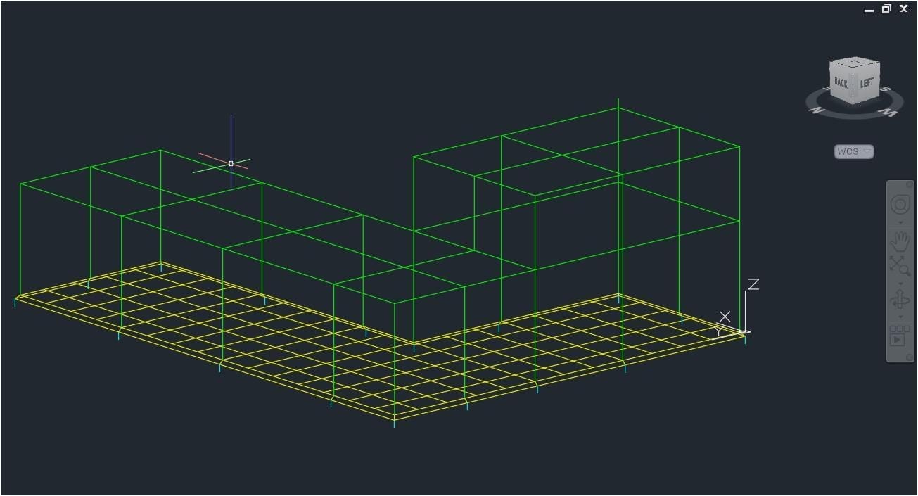
In the example an earthing system was drawn in CAD in 3D and imported into SafeGrid. The earthing system consists of buried grid, buried rods, and above-ground segments. These were drawn using Lines , but entities drawn in Polylines, LWPolylines, Circles ,or Arcs are also supported.

Figure 3– Example earthing system drawn in CAD

Select the lines or the layers to import which can be selected according to your requirements:

3.1 Importing the CAD file into SafeGrid

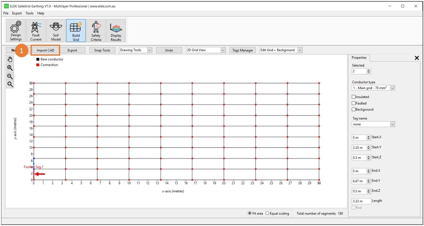
Go to the Build Grid module in SafeGrid to import your file.
The number one in a yellow circle representing renewables.
Click Import then select the DXF file you want to import.
Figure 4 – Import an AutoCAD file

3.2 Import Grid from CAD File settings

The settings in Import Grid from CAD File will help you import grid from DXF file.
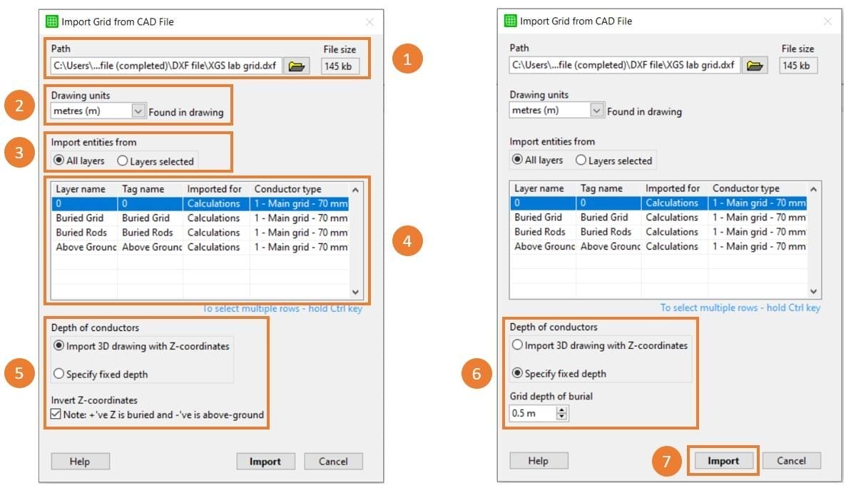
Figure 5 – Import Grid from CAD File settings
The number one in a yellow circle representing renewables.
Select the DXF file to import. The path of the currently loaded DXF file is displayed and the user can also select a different file.
A yellow circle with the number two representing renewable power.
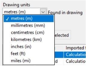
Select the Drawing units. The units set in the drawing file will be displayed here or if they haven’t been set, they can be selected here from the Drawing units dropdown.
Figure 6 – Select the drawing units
Select the drawing layer(s) to import:
The yellow circle represents the number 3 in an electrical world.
Select either to load All layers or Layers selected. Select layer names in the table below for the latter and hold Ctrl key to select multiple layers.
A yellow circle representing a digital electrical substation with the number 4.
Select and configure Layer properties table:
  • a) Layer name – Layer names read from DXF file are displayed here.
  • b) Tag name – Specify tag names of layers. The segments with the same tag name can be quickly included/excluded for the calculations later. Tag names can also be modified after the import. Layer names are used as default tag names
  • c) Imported for – Layers can be imported for calculations or as the background which can also be changed in the main UI after the import.
  • d) Conductor type – Select the conductor type for the layers which were defined under Design Settings. Conductor types are settable in the Design Settings window.
Set depth of burial. SafeGrid needs z depth for the lines being imported:
bullet 5 - Load Grid from DXF AutoCAD File
For drawings in 3D, use the z-coordinates in the DXF file with Import 3D drawing with Z-coordinates.The z-coordinates direction can also be inverted as required. Note that positive z-coordinates denote buried segments.
bullet 7 - Load Grid from DXF AutoCAD File
For drawings in 2D, give all segments with the same depth by selecting Specify fixed depth and specifying the depth.
bullet 6 - Load Grid from DXF AutoCAD File
Press the Import button to load the grid.

3.3 Import Summary

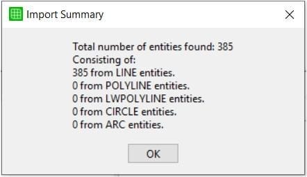
After the import,the Import Summary window is displayed. The Import Summary lists the CAD entities found.

The user should verify the Import Summary and make sure the intended entities have been imported correctly.
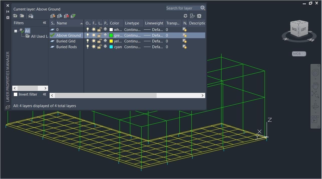
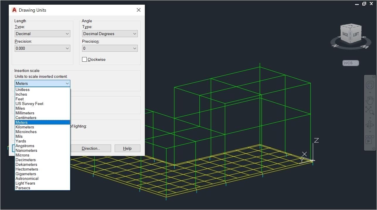
Figure 7 – Import Summary window
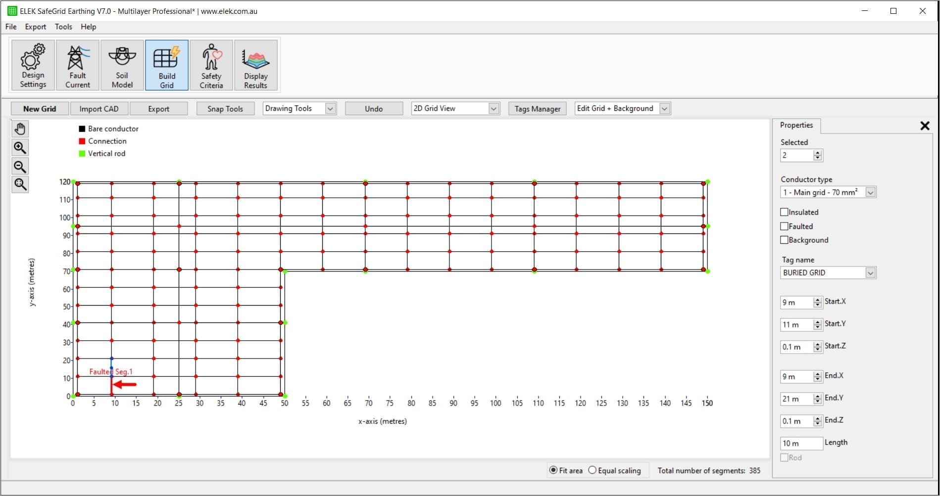
Pressing OK button in the Import Summary window (Figure 7) will load the earthing grid to the drawing area of the Build Grid module.The imported grid can be further modified using the in-built editor (for example you can add rods). It can also be saved along with the SafeGrid project file.
Figure 8 – Imported earthing system

Related Tutorials:

This tutorial shows how to use the Fault Current Distribution module in ELEK SafeGrid Earthing Software to model an earth fault on an overhead transmission line with an underground cable link.
With the Fall of Potential Test, the resistance of an earthing system is measured using a remote earth electrode. There is a theoretical position of 61.8 % of the separation distance between the measured grid and the remote electrode, which is the correct position for measuring the exact grid impedance for uniform soil resistivity but not for multilayer soils. This tutorial shows ELEK SafeGrid Earthing Software users how to simulate an FOP test.
This video tutorial focuses on the design and modelling of Earthing Systems for Wind Farms and Solar PV Farms. Real-world examples are provided and are explained.
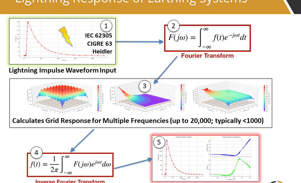
ELEK SafeGrid Earthing Software can perform calculations in the time domain such as for lightning currents. Transient waveforms are composed of many frequency components and Fourier transforms are used. The transient waveform types include IEC 62305, CIGRE, Heidler, Double-exponential, and Custom. The time-domain response of an earthing system can be analysed.
This video (25 min) tutorial shows the main features of SafeGrid Earthing Software for performing an earthing designs and explains the design process.
Example Rolling Sphere Method calculation which shows how to overlay protection systems such as lightning masts and earth wires on a site drawing.