ELEK SafeGrid Earthing Software can perform calculations in the time domain such as for lightning currents. Transient waveforms are composed of many frequency components and Fourier transforms are used. The transient waveform types include IEC 62305, CIGRE, Heidler, Double-exponential, and Custom. The time-domain response of an earthing system can be analysed.


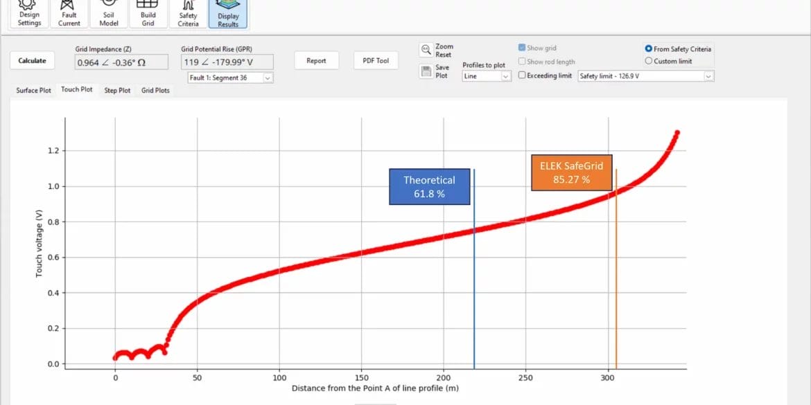
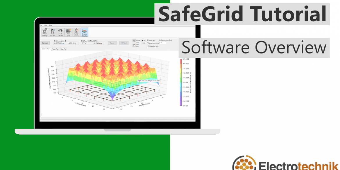
 - Display Results")
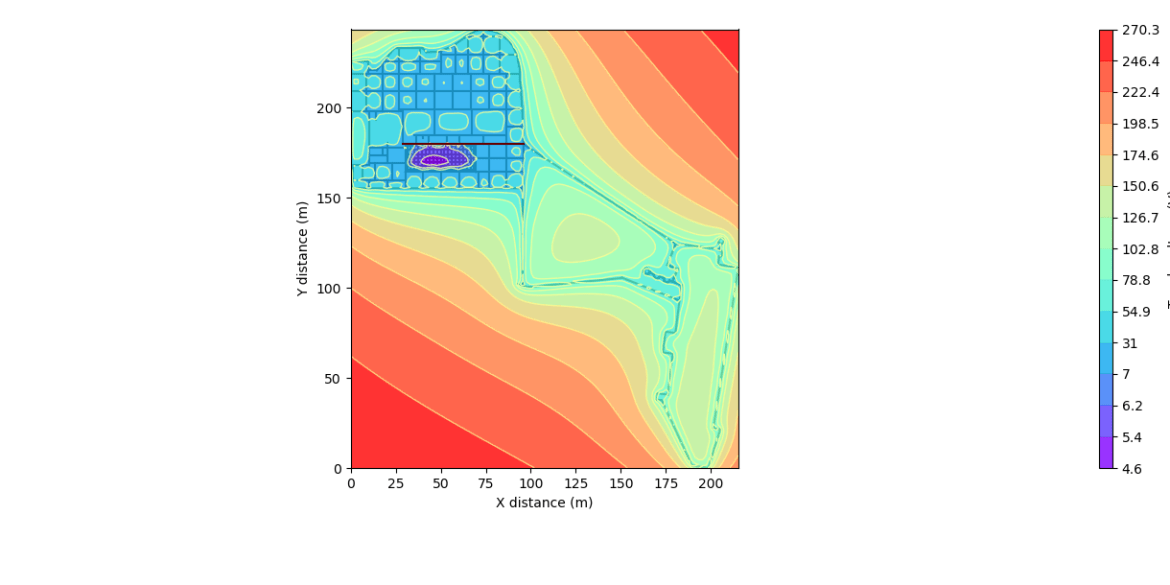
 - Unsafe area in terms of touch voltages")