Table of Contents
Introduction
ELEK Cable Pulling SoftwareTM can calculate tensions for cable sections. You can specify the cable sections directly in the Cable Pulling UI or you can import cable sections drawn in AutoCAD in 3D.
It is easy to draw cable sections in AutoCAD® as connected entities, then save them in the DWG or DXF file format and import them into ELEK Cable Pulling SoftwareTM for calculations. This tutorial will show you how.
1. Rules for importing
The rules of drawing cable sections and importing into CAD are as follows:
- a) Cable pulling sections drawing should be saved as an DWG or ASCII DXF file.
- b) Set the measurement units of the AutoCAD drawing to be in Meters, Centimetres, Millimetres, Inches, or Feet. The sections of the pull will be imported and converted into meters.
- c) Cable sections should be drawn using Lines, Polylines, LWPolylines, or Arcs entities.
- d) Two (only) open ends of the cable pull must exist at the start and end of the pull.
- e) The start of the pull will be automatically detected as being the open end that is closest to the drawing origin (0,0,0) m.
- f) All sections of the cable pull must be connected end-to-end without discontinuity. Two sections are deemed to be connected if they are located within 1 mm.
- g) The cable pull must not consist of multiple paths (branches).
- h) The ground level is assumed to be along the x-y plane. The z-axis is either in an upwards (positive) or downwards (negative) direction.
- i) An arc that is in parallel with the x-y plane will be identified as a horizontal bend whereas an arc in parallel with the z-axis will be identified as either a concave or convex bend. If the arc is not parallel with the x-y plane or the z-axis, an error will occur.
2. Drawing the cable pull
Draw your cable pull as sections in AutoCAD (or equivalent software) by specifying connected straight lines, polylines, or arcs.
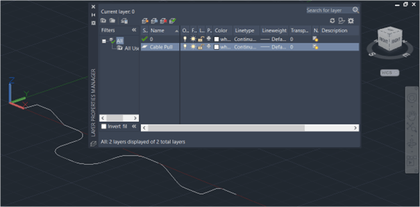
You can add cable pulling sections to an existing drawing, just make sure to create a unique and independent drawing layer or layers for each unique cable pull. For example, the cable section layer in Figure 2 is named ‘Cable Pull’.
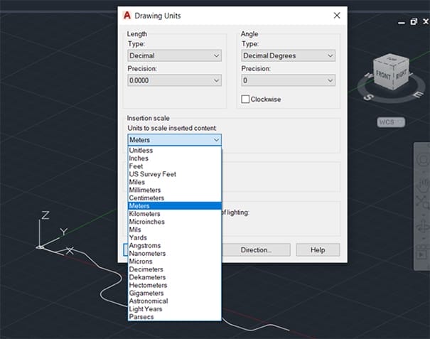
Set the drawing units of the file in AutoCAD using the UNITS command otherwise if they are not set in the drawing then they can also be specified while importing the drawing into ELEK Cable Pulling SoftwareTM.
Once the cable pulling AutoCAD drawing is completed and ready to be imported into the cable pulling software then save the drawing as DWG (.dwg) or ASCII DXF (.dxf) or file format.
3. Example of a cable pull
In the example a complete cable pulling arrangement from start to end was drawn in CAD and imported into the cable pulling software. The pull consists of straight (horizontal) and vertical up and down sections, these were drawn using lines, and bends (horizontal, convex/concave upward/downward) that were drawn using arcs.

The example cable pull shown in Figure 3 contains the following sections:
Table 1 – Summary table of cable sections
| No. | Type | Properties | AutoCAD Entity |
|---|---|---|---|
| 1 | Straight or Horizontal | Length: 10 m |
LINE Start (x=0,y=0,z=0) m; End (x=10,y=0,z=0) m |
| 2 | Slope Up | Length: 11.18 m; Angle: 27° |
LINE Start (x=10,y=0,z=0) m; End (x=20,y=0,z=5) m |
| 3 | Straight or Horizontal | Length: 10 m |
LINE Start (x=20,y=0,z=5) m; End (x=30,y=0,z=5) m |
| 4 | Slope Down | Length: 11.18 m; Angle: 27° |
LINE Start (x=30,y=0,z=5) m; End (x=40,y=0,z=0) m |
| 5 | Straight or Horizontal | Length: 10 m |
LINE Start (x=40,y=0,z=0) m; End (x=50,y=0,z=0) m |
| 6 | Horizontal Bend | Radius: 10 m; Angle: 90°; Bend Direction: Right |
ARC Centre (x=50,y=-10,z=0) m; Radius 10 m; Start Angle 0°; End Angle 90° |
| 7 | Straight or Horizontal | Length: 10 m |
LINE Start (x=60,y=-20,z=0) m; End (x=60,y=-10,z=0) m |
| 8 | Horizontal Bend | Radius: 10 m; Angle: 90°; Bend Direction: Left |
ARC Centre (x=70,y=-20,z=0) m; Radius 10 m; Start Angle 180°; End Angle 270° |
| 9 | Straight or Horizontal | Length: 10 m |
LINE Start (x=70,y=-30,z=0) m; End (x=80,y=-30,z=0) m |
| 10 | Horizontal Bend | Radius: 10 m; Angle: 90°; Bend Direction: Left |
ARC Centre (x=80,y=-20,z=0) m; Radius 10 m; Start Angle 270°; End Angle 0° |
| 11 | Straight or Horizontal | Length: 10 m |
LINE Start (x=90,y=-20,z=0) m; End (x=90,y=-10,z=0) m |
| 12 | Horizontal Bend | Radius: 10 m; Angle: 90°; Bend Direction: Right |
ARC Centre (x=100,y=-10,z=0) m; Radius 10 m; Start Angle 90°; End Angle 180° |
| 13 | Straight or Horizontal | Length: 10 m |
LINE Start (x=100,y=0,z=0) m; End (x=110,y=0,z=0) m |
| 14 | Convex Downward Bend | Radius: 10 m; Angle: 30° |
ARC Centre (x=110,y=0,z=-10) m; Radius 10 m; Start Angle 60°; End Angle 90° |
| 15 | Slope Down | Length: 10 m; Angle: 30° |
LINE Start (x=115,y=0,z=-1.34) m; End (x=123.66,y=0,z=-6.34) m |
| 16 | Concave Downward Bend | Radius: 10 m; Angle: 30° |
ARC Centre (x=128.66,y=0,z=2.32) m; Radius 10 m; Start Angle 240°; End Angle 270° |
| 17 | Straight or Horizontal | Length: 10 m |
LINE Start (x=128.66,y=0,z=-7.68) m; End (x=138.66,y=0,z=-7.68) m |
| 18 | Concave Upward Bend | Radius: 10 m; Angle: 30° |
ARC Centre (x=138.66,y=0,z=2.32) m; Radius 10 m; Start Angle 270°; End Angle 300° |
| 19 | Slope Up | Length: 10 m; Angle: 30° |
LINE Start (x=143.66,y=0,z=-6.34) m; End (x=152.32,y=0,z=-1.34) m |
| 20 | Convex Upward Bend | Radius: 10 m; Angle: 30° |
ARC Centre (x=157.32,y=0,z=-10) m; Radius 10 m; Start Angle 90°; End Angle 120° |
| 21 | Straight or Horizontal | Length: 10 m |
LINE Start (x=157.32,y=0,z=0) m; End (x=167.3,y=0,z=0) m |
3.1 Importing the CAD file
Go to the Cable Pulling Main Window to import your file.
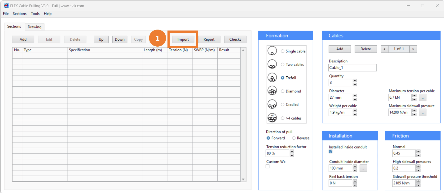
1 Click Import then select the AutoCAD file you want to import.
3.2 Importing the sections
Settings in Import Sections from CAD File will help you import cable sections from DWG or DXF file.
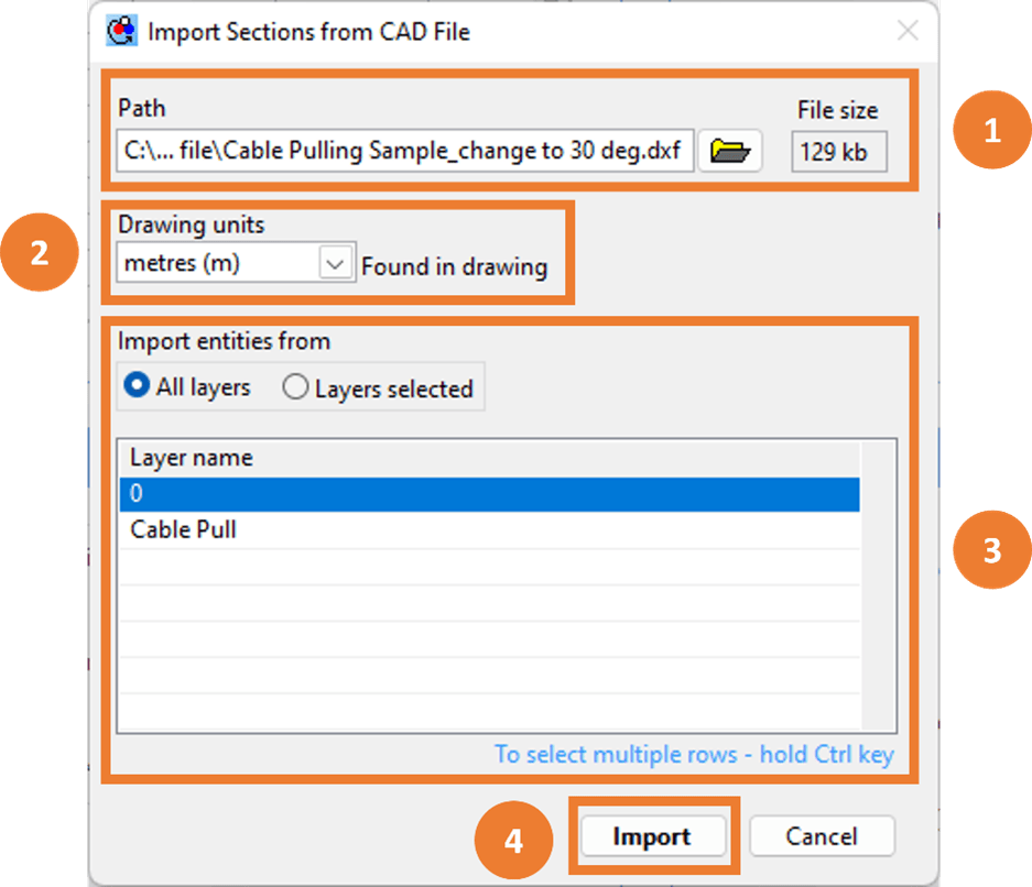
1 Select the DWG or DXF file to import. The path of the currently loaded file is displayed and the user can also select a different file.
2 Select the drawing units. The units set in the drawing file will be displayed here or if they haven’t been set they can be selected here from the Drawing units dropdown.
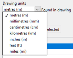
Select the drawing layer(s) to import:
3 Select either to load All layers or Layers selected. Select layer names for the layers.
4 Press Import button to load cable sections.
3.3 Import Summary
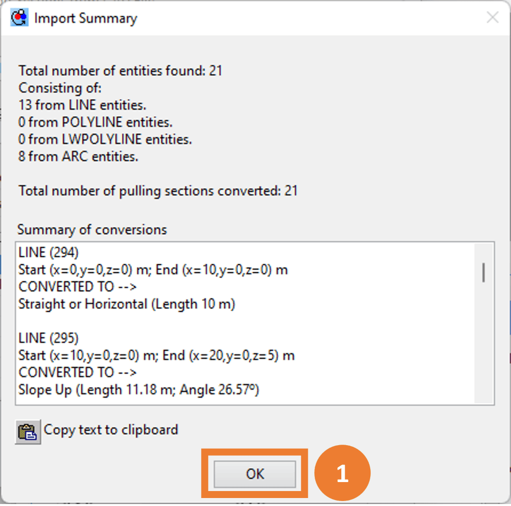
After importing the Import Summary window is displayed. The Import Summary lists the CAD entities found and how each has been converted to a pulling section.
The user should verify the Import Summary and make sure the intended cable sections have been imported and converted correctly.
3.4 Calculating the results
1 Pressing OK button in the Import Summary window (Figure 7) will load the identified cable sections to the Sections area of the cable pulling software and the pulling tension calculations will be performed automatically.
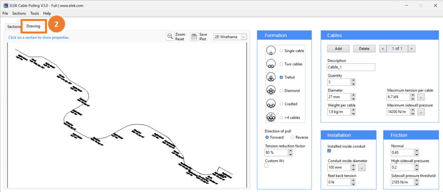
2 Clicking on the Drawing tab will show you the drawing of the cable pull in 2D and 3D.
Note that the cable pull can be modified by inserting additional section types (such as rollers or push/pull machines) into the run. The Direction of pull can be changed to investigate the different maximum pulling tensions and sidewall pressures of the cables.

