Introduction
The Transient Rating Module of ELEK Cable HV Software is explained in this tutorial.
In this video, we explain how to perform emergency and cyclic rating calculations for high-voltage power cables using the software.
For detailed technical information refer to our article Emergency and Cyclic Ratings of HV Cables.
Capabilities
The software has the following capabilities:
- The transient temperature response of a cable can be calculated for a user-specified load factor for 24 hours (as recommended in IEC 60853).
- Emergency current ratings for user-specified load factor with percentage pre-loaded current.
- Cyclic ratings using the IEC 60853 method or the Neher-Mcgrath method.
- The effect of change in conductor resistance with temperature is incorporated in the calculations.
Definitions
The definition of emergency rating is the permissible short-term rating of a cable already loaded and at a steady state, considering the thermal capacitances and the thermal resistances of an installed cable system.
The definition of cyclic rating is the maximum current of a cable when the load is varied in a sequence of steps that are repeated cyclically. The cyclic rating differs for different sequences and different cycle periods.
Both emergency and cyclic ratings deal with time-varying loads.
The methods of calculating emergency and cyclic ratings of cables used in the software are based on the IEC Standards. According to the Standards emergency ratings are applicable both for cables installed in air and buried cables (direct, in backfill or in ducts) whereas cyclic ratings only apply for buried cables.
Thermal ladder network
The standard deals with time varying loading by representing the physical cable system and its surroundings using a thermal ladder network of thermal resistances in series and capacitances in parallel where heat flow within the cable emanates radially to the outside of the cable and onto the environment. The figure shows the thermal ladder network model for a multicore high voltage cable.
Transient temperature response
A fundamental part of the transient calculations is to determine the transient temperature response for the cable. The transient temperature response is the response to a step of sustained rated load current. The transient calculations along with values from steady state rating calculations, are both used as inputs to the emergency and cyclic rating calculations.
This plot displays the change in conductor temperature above ambient due to a step in load current. It does not show the actual temperature attained during the emergency or cyclic loading.
Emergency current rating
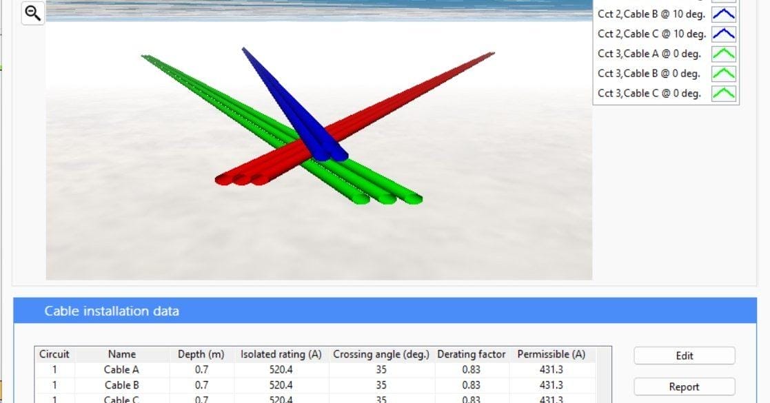
To perform an emergency current rating calculation create a steady-state rating calculation and open the Transient Rating Module. Notice the title of the window confirms whether the cables are in air or buried cables, which affects the calculations.
Select the circuit to study from the dropdown. Note that for emergency and cyclic rating calculations the cable circuits are assumed to be in isolation. Under the Emergency rating inputs set the load factor and the transient time. You should set the transient time to be longer than the emergency rating duration but it has a maximum of 24 hours as per the IEC standard. Set the Maximum emergency temperature, which is the allowable conductor temperature attainable during the emergency event. Emergency rating will increase for a shorter emergency time and if the loading prior to the emergency is lower.
Cyclic current rating
There are two methods for calculating the cyclic rating, the IEC method and the Neher-McGrath method.
The IEC calculation method for cyclic ratings requires the user to input an hourly load profile for a minimum of six hours. Typically the custom load profile data will cover a 24 hour period, but it can be for longer than 24 hours or a shorter time period.
The user can manually specify the loaded current for each hour or import a custom load profile as a CSV file. A current value can be specified at a time (hour) or for a duration. The Duration setting is easier to use for longer periods such as over hundreds or thousands of hours of load data.
The Neher-McGrath method is available and uses the Load factor value under the Emergency rating inputs.
Report
A detailed report is generated by pressing the Report button. There are two main sections to the report, the inputs and the results.
The Inputs section contains the name of the circuit and it’s steady-state rating. The emergency and cyclic rating calculation inputs are also shown.
The Results section includes the calculated Transient response values along with the transient temperature response plot. There is also the emergency and cyclic rating results and plots.