目录
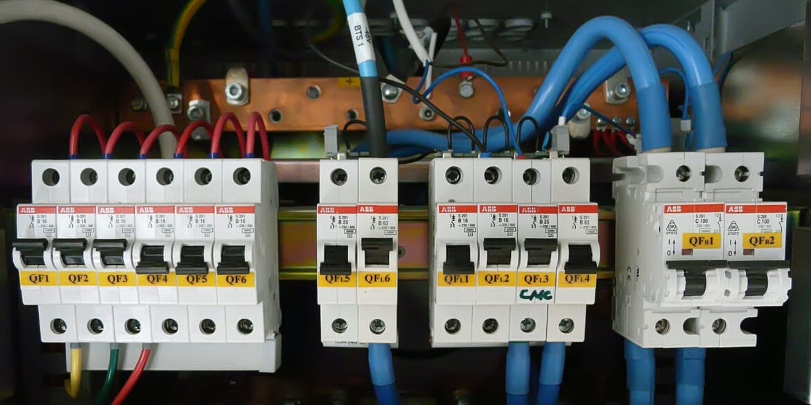
短路电缆额定值
在短路期间,流过的故障电流(在保护装置中断之前)会导致电力电缆温度急剧上升。故障时电缆内部产生的热量取决于导体尺寸和材料以及故障电流和持续时间。
电力电缆可承受的温度极限是电缆绝缘层的极限温度。绝缘的温度限制取决于其材料类型,高于正常工作温度限制,因为故障发生的时间很短。
因此,有一个最小导体尺寸(特定电缆类型--公式中包含的数量随电缆中使用的材料而变化)来承受一定的故障电流和相关故障时间。低压电力电缆主导体的短路额定值是确定电力电缆尺寸时需要考虑的重要因素,同时还要考虑载流量和压降。
以下标准要求设计人员计算电力电缆中导体的短路额定值:AS/NZS 3008.1、BS 7671 和IEC 60364。
绝热法与非绝热法
The adiabatic method is used to calculate the minimum conductor size or another current-carrying conductor when heat loss from the current-carrying component during the short circuit is neglected. The adiabatic method is a conservative approach, that is valid for short-circuit duration of up to 5 s.
The non-adiabatic method, on the other hand, assumes an appropriate allowance for heat loss into the insulation during the short circuit, which is applicable for all short-circuit durations. The non-adiabatic short-circuit rating is determined by calculating a modifying factor that takes into account the non-adiabatic heating effect and applying it to the adiabatic short-circuit rating.
In comparison, the non-adiabatic method will provide significant increases in the permissible short-circuit ratings of metallic screens, sheaths, and small conductors < 10 mm2. However, the non-adiabatic method is more complicated and in practice for the usual range of power cable conductors, there will be less than a 5 % difference in the short-circuit rating obtained using the adiabatic method.
In general, when the ratio of the conductor size to short-circuit duration is > 10 (mm2/s) the increase in short-circuit rating is negligible and the adiabatic method can be used.
计算承受短路电流的最小横截面积
下式基于绝热法,该方法通常用于确定低压电力电缆的短路额定值。如前所述,绝热法适用于最长 5 秒的短路持续时间。
\S_{min} = \sqrt\frac{I^2t}{K^2}}\)
地点
I是短路电流(r.m.s 超过持续时间),单位为安培。
t 是短路持续时间,单位为秒。
K 是常数,取决于载流部件的材料、载流部件的初始温度和最终温度。
S 是载流部件的横截面积,单位为平方毫米。
K 因子计算
The calculation of K factor refers to the International Standard IEC 60364-5-54 Annex A.
The K factor is calculated from the formula below:
\(K = \sqrt{\frac{Q_c(\beta+20)}{\rho_{20}}\ln\frac{\beta+\theta_f}{\beta+\theta_i}}\)
The K factor is calculated from the formula below:
\(K = \sqrt{\frac{Q_c(\beta+20)}{\rho_{20}}\ln\frac{\beta+\theta_f}{\beta+\theta_i}}\)
Where
\(Q_c\)is the volumetric heat capacity of conductor material (J/K mm3) at 20 °C;
\(\beta\)
is the reciprocal of temperature coefficient of resistivity at 0 °C for the conductor (°C);
\(\rho_{20}\)is the electrical resistivity of conductor material at 20 °C (Ω.mm);
\(\theta_i\)
is the initial temperature of conductor (°C);
\(\theta_f\)
is the final temperature of conductor (°C).
不同材料的参数值如下所示。
电缆的短路温度限制
如上公式所示,计算 K 系数需要导体的初始温度和最终温度。标准中有各种表格提供初始和最终温度限制或指定 K 值,或两者兼而有之。
短路电流和持续时间
使用的短路电流应基于电气系统中的实际故障电流,可使用 "故障研究 "软件进行计算。在确定特定电缆的短路额定值时,有人可能会问,应该使用电缆起点还是终点的故障级别(短路电流)。
根据澳大利亚标准 AS/NZS 3000,电路中任何一点的短路电流都应在导体温度达到允许极限之前中断。在计算中,使用电缆起点的短路电流是比较保守的。
另一方面,在英国标准 BS 7671:2018 中,短路电流应为有效值的有效故障电流,其中适当考虑了电路阻抗的限流效应。因此,可以使用电缆末端的短路电流。
根据澳大利亚标准 AS/NZS 3000,电路中任何一点的短路电流都应在导体温度达到允许极限之前中断。在计算中,使用电缆起点的短路电流是比较保守的。
另一方面,在英国标准 BS 7671:2018 中,短路电流应为有效值的有效故障电流,其中适当考虑了电路阻抗的限流效应。因此,可以使用电缆末端的短路电流。
参考资料
AS/NZS 3008.1:电气装置--电缆的选择,第 1.1 部分:0.6/1 千伏及以下交流电压用电缆
BS 7671 - 第 18 版 IET 布线规范
IEC 60364-5-54 建筑物电气装置 - 第 5-54 部分:电气设备的选择和安装 - 接地安排、保护导体和保护接合导体
IEC 60364-4-43 低压电气装置--第 4-43 部分:安全保护 - 过电流保护
BS 7671 - 第 18 版 IET 布线规范
IEC 60364-5-54 建筑物电气装置 - 第 5-54 部分:电气设备的选择和安装 - 接地安排、保护导体和保护接合导体
IEC 60364-4-43 低压电气装置--第 4-43 部分:安全保护 - 过电流保护