Equations for calculating earthing rod resistance validated with software
How earthing rods improve safety
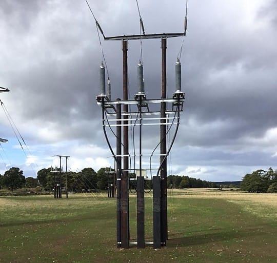
Earthing rods are bare metal stakes driven vertically into the ground installed as standalone or in groups as part of an earthing system. Earthing rods may improve safety by reducing earthing grid resistance and reducing touch voltages when driven into low resistivity soil layers.
For larger earthing systems multiple rods may be connected in the form of rod beds. The individual rods of rod beds should not be installed too close to one another due to the proximity effect which reduces their efficiency. Figure 1 shows how the fields of rods affects other rods while they are dissipating current into the ground during a fault.
The general rule of thumb is earth rods should be separated by at least their driven length.
Figure 1 - Proximity effect between two adjacent earth rods
Should earthing rods be encased in concrete?
IEEE Std. 80 [ref. 1] states that encasing rods in concrete may be effective at improving the performance of buried rods. Our article on Concrete-encased Earthing Rods explains more.
Calculating earthing rod resistance
Equations for calculating resistance of individual rods, groups of bare rods and rods encased in concrete are given below. There is also a free Earth Rods Resistance Calculator.
Example calculations are given below and the results are validated with SafeGrid Earthing Software.
Single earthing rod equation
Die übliche Formel zur Berechnung des Widerstands eines einzelnen Stabs [1] lautet:
Wo:
ρ:the resistivity of the soil (Ω.m) Lr:length of the rod d: diameter of the ground rod.
Rods bed equation
The simple equation used to calculate the rods bed resistance is given by Schwarz [ref. 1] as:
Wo:
ρ: Soil resistivity (Ω.m) nr: Number of rods Lr: Length of rod (m) d: diameter of the rod (mm) A: Grid area (m2) K1: coefficients
The coefficient K1 formula was given by Kercel [ref. 2] as:
Where a is the length of the grid and b is the width of the grid.
Rods bed encased in concrete equation
To reduce the soil resistivity around the rod (thus making it more effective) a low resistivity layer is added around it to increase its effectiveness while lowering the cost of materials. With the inclusion of concrete in equation (1), we get the following equation:
Where: ρc: the resistivity of concrete (Ω.m) Dc: Diameter of the concrete shell (mm)
Example hand calculations and software validation
Example 1 – Rods bed resistance
In this example we calculated the resistance of a 20 m by 10 m meshed grid shown Figure 2 which had 15 rods which are 5 m long buried at 0.5 m and were each separated by 5 m. The soil model is 100 Ω.m uniform.
Note that Equation 2 does not consider the effects of the horizontal connected conductors, which is a drawback of the simple equation approach. Therefore, in the SafeGrid software model the horizontal conductors connecting the tops of the rods together were insulated.
For the rod bed in Figure 2, Equation 2 gives a resistance of 3.19 Ω. SafeGrid software calculates 2.851 Ω for the same rod bed arrangement which is 10.6 % lower.
Figure 2. Software model of rods bed with insulated horizontal conductors
Figure 3. Software results for rod bed
To examine the proximity effects, we varied the spacing between the 5 m rods from 1m (separation factor = 0.2) up to 10 m (separation factor = 2) and calculated resistance.
Figure 4 shows that the simple rod bed resistance equation captures the proximity effect as confirmed by the SafeGrid software model results. The optimal separation between rods is when the separation distance is equal to the rod length.
Figure 4. Rod bed resistances of bare rods
Example 2 – Concrete-encased rod bed resistance
In this example the grid is the same as in Example 1 except the rods are encased in concrete with a shell diameter of 200 mm. and the concrete has resistivity of 30 Ω.m which is lower than the native soil resistivity of 100 Ω.m uniform.
For the rod bed in Figure 5, Equation 4 gives a resistance of 2.96 Ω which is lower than the result in Example 1 without concrete encasing of rods.
SafeGrid software calculates the resistance for the concrete-encased rod bed to be 2.545 Ω.
Figure 5. Software model of concrete-encased rods bed with insulated horizontal conductors
Figure 6. Software results for concrete-encased rod bed
To examine the proximity effects, we varied the spacing between the 5 m rods from 1m (separation factor = 0.2) up to 10 m (separation factor = 2) and calculated resistance.
Figure 7 shows how rod bed resistance varies for concrete-encased grid using the simple equation and using SafeGrid software. Once again, the plot confirms that optimal separation between rods is when the separation distance is equal to the rod length.
Figure 7. Rod bed resistances of concrete-encased rods
Empfehlungen
The simple equations from IEEE Std. 80 [ref. 1] for rod resistance and rod bend resistance have been extended to include the effects of concrete-encasing of the rods. The simple equations appear to capture the proximity effect for rods reasonably.
The significant limitations of using the simple equations includes:
They can only model simple rod arrays with equal separations.
They cannot model the horizontal interconnecting conductors.
They are limited to only uniform soil models.
Most soils have a multilayer soil resistivity structure. Importantly, rods should in general be used when the bottom layer resistivity is lower than the top layers and the rods should be sufficiently long to penetrate the low resistivity layers.
The significant advantages to using software to model earthing systems includes:
Software can model arbitrary earthing arrangements for multi-layered soils resistivity structures.
Software results are more accurate resulting in higher degrees of safety and cost savings due to more economical earthing system installations.
Referenzen:
[1] ‘IEEE Guide for Safety in AC Substation Grounding.’ IEEE Std. 80-2013. [2] Kercel, S. W., “Design of switchyard grounding systems using multiple grids” IEEE Transactions on Power Apparatus and Systems, vol. PAS-100, no. 3, pp. 1341–1350, Mar. 1981.
SafeGrid Erdungs-Software
Einfaches Entwerfen sicherer Erdungssysteme in Übereinstimmung mit den Normen.
Erfahrene Elektroingenieure haben diese Referenzliste mit Normen für die Erdung von Stromversorgungssystemen für Umspannwerke, erneuerbare Energien usw. erstellt.
Verstehen Sie, wie Softwaresimulationen die Netzimpedanzprüfungen verbessern und damit die Genauigkeit und Effizienz bei der Planung von Erdungssystemen und der Leistungsbewertung erhöhen.
In diesem Bericht wird erläutert, wie eine genaue Erdschlussstromanalyse für Umspannwerke, die über Kabelübertragungsleitungen angeschlossen sind, durchgeführt werden kann. Zunächst werden Erdschlussströme für einfache Kabel- und Freileitungen erläutert. Anschließend werden zwei Fallstudien mit hybriden Kabelübertragungsleitungen vorgestellt.
Kupfer wird oft wegen seiner überlegenen elektrischen Eigenschaften bevorzugt, während Aluminium und verzinkter Stahl wegen ihrer Kosteneffizienz gewählt werden. Kupferbeschichteter Stahl kann ein Gleichgewicht zwischen Kosten und Leistung bieten. Dieser Artikel zeigt, welche Option für verschiedene Szenarien am besten geeignet ist.
Der technische Leitfaden erläutert die elektrischen Systeme, die Auslegung lokaler WEA und kombinierter Erdungssysteme, die Gefährdung durch Berührungs- und Schrittspannung, die Messung des elektrischen Bodenwiderstands, Erdschlussströme, die Modellierung von Erdungssystemen und die Validierungsprüfung der Erdung von Windparks.