목차
Short-circuit cable ratings
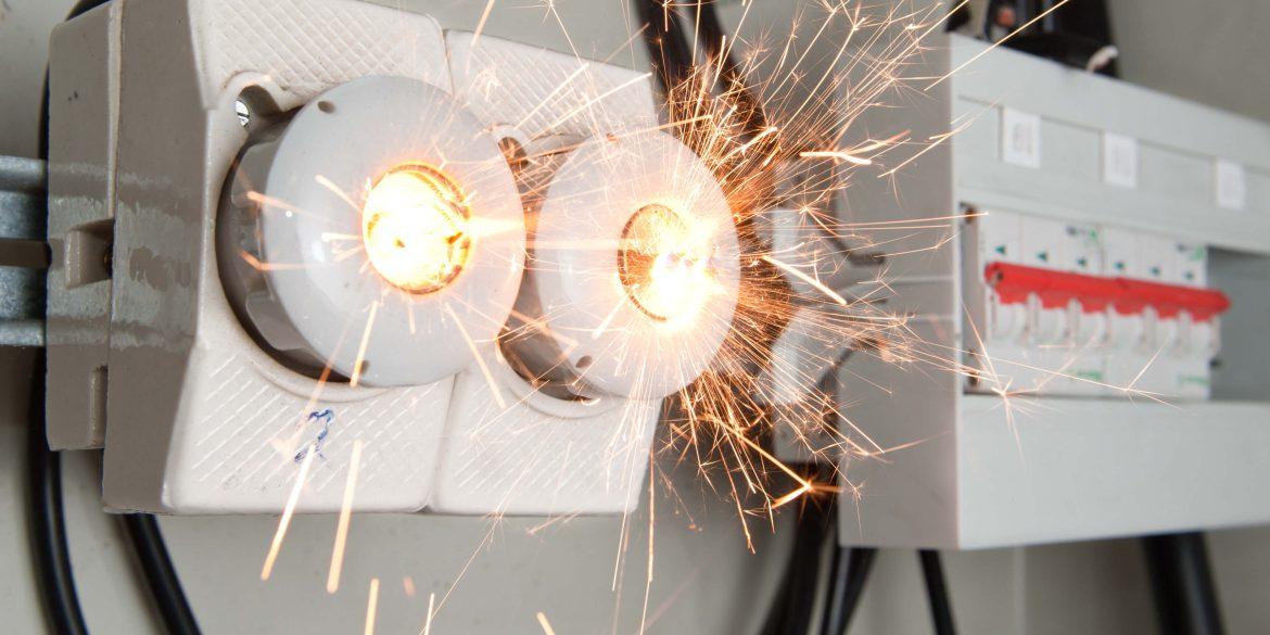
During a short circuit, the fault current that flows (before the protective device interrupts) causes the temperature of the power cables to rise dramatically. The heat generated inside the cable during a fault depends on the conductor size and material as well as the fault current and its duration.
There are temperature limits that power cables can withstand where the limiting temperature is that of the cable insulation. The temperature limits of the insulation, which depend on their material type, are higher than the normal operating temperature limits since faults occur only for a short time.
Therefore, there is a minimum conductor size (of a particular cable type – the formulae contain quantities that vary with the materials used within the cables) required to withstand a certain fault current and the associated fault time. Short circuit rating of the main conductors of low-voltage power cables is an important factor to consider when sizing power cables alongside current-carrying capacity and voltage drop.
The following standards require designers to calculate the short-circuit rating of the conductors in power cables: AS/NZS 3008.1, BS 7671, and IEC 60364.
Adiabatic versus non-adiabatic method
The non-adiabatic method, on the other hand, assumes an appropriate allowance for heat loss into the insulation during the short circuit, which is applicable for all short-circuit durations. The non-adiabatic short-circuit rating is determined by calculating a modifying factor that takes into account the non-adiabatic heating effect and applying it to the adiabatic short-circuit rating.
In comparison, the non-adiabatic method will provide significant increases in the permissible short-circuit ratings of metallic screens, sheaths, and small conductors < 10 mm2. However, the non-adiabatic method is more complicated and in practice for the usual range of power cable conductors, there will be less than a 5 % difference in the short-circuit rating obtained using the adiabatic method.
In general, when the ratio of the conductor size to short-circuit duration is > 10 (mm2/s) the increase in short-circuit rating is negligible and the adiabatic method can be used.
Calculation of the minimum cross-section area to withstand short-circuit current
Where
I is the short-circuit current (r.m.s over duration), in amperes.
t is the duration of short circuit, in seconds.
K is the constant depending on the material of the current-carrying component, the initial temperature and final temperature of the current-carrying component.
S is the cross-sectional area of the current-carrying component, in square millimetres
K-factor calculations
The K factor is calculated from the formula below:
\(K = \sqrt{\frac{Q_c(\beta+20)}{\rho_{20}}\ln\frac{\beta+\theta_f}{\beta+\theta_i}}\)
Short-circuit temperature limits for cables
Short-circuit current and duration
As per the Australian Standard AS/NZS 3000, the short-circuit current at any point of a circuit shall be interrupted before the temperature of the conductors reaches the permissible limit. Since it is conservative to use the short-circuit current at the start of the cable in the calculation.
On the other hand, in the British Standard BS 7671:2018, the short-circuit current should be the effective fault current as the RMS value, where the due account is taken of the current limiting effect of the circuit impedances. Therefore, the short-circuit current at the end of the cable may be used.
참조:
BS 7671 – 18th Edition The IET Wiring Regulations
IEC 60364-5-54 Electrical installations of buildings – Part 5-54: Selection and erection of electrical equipment – Earthing arrangements, protective conductors and protective bonding conductors
IEC 60364-4-43 Low-voltage electrical installations – Part 4-43: Protection for safety – Protection against overcurrent


