Concrete is hygroscopic which means it absorbs water and when concrete is buried, depending on the moisture levels at the time of the surrounding soil, it behaves as a semiconducting medium. Concrete has a typical electrical resistivity of between 30 Ohm.m to 200 Ohm.m [1]. It has been measured that wet concrete resistivity is almost uniform throughout whereas regular concrete has an equivalent two layer model consists of a bottom layer having a resistivity of 1244 Ohm.m with 195 Ohm.m for the top layer (interestingly the resistivity of concrete increases with depth/thickness).
Because of the relatively low resistivity of concrete it is known that metallic earthing rods which are encased inside concrete will have a lower resistance to ground at both power frequency and at lightning impulse levels than the same rod which is directly buried into the earth [4].
Therefore concrete encasing of earthing rods can be used to reduce their ground resistance and improve overall earthing system performance. However, it is a costly measure and should be undertaken with some measure of caution. Where there is adequate real estate it may be a better option simply to increase the number of directly buried rods while ensuring adequate horizontal separations (separate them by at least their driven length – read our article on the Fundamentals of Earthing Design) to reduce the proximity effect between multiple buried rods.
There are empirical equations for calculating the resistance for both direct buried and concrete encased earthing rods. There are more accurate methods (described in our article [7]) for modelling concrete encased rods using numerical software.

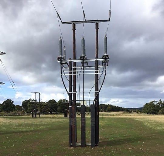
Concrete pole bases of transmission lines can act as grounding structures in distribution systems where they have been shown to be a viable and economical alternative in substitution to individual rods especially in high resistivity soils [4]. In the case of low resistivity soils the base pole resistance is larger than that of a single rod. On the other hand, the opposite is observed for high resistivity soil. The same methods described in article [7] can be used for modelling concrete pole foundations for earthing.
The main problems with concrete encased earthing rods are caused to corrosion of the steel reinforcement embedded inside the concrete. When rebar corrodes it expands to about 2.2 times its original volume which can split the concrete foundation. The corrosion of rebar is caused by the flow of stray DC current. The steel rebar and the earthing conductor are electricall connected through the semi-conducting concrete medium. Even if stray DC currents are not present, it’s been shown approximately 0.01% of the AC current which flows into the ground is rectified at the interface of steel and concrete [1]. However, it has also been shown that below a threshold of about 60 V DC that corrosion will not occur.
Note that the rebar inside concrete should always be directly bonded with the earthing since this can reduce the touch voltages significantly (up to 83% in wet conditions) [2].
参考资料
- IEEE Std 80-2013, “IEEE Guide for Safety in AC Substation Grounding”.
- EPRI, “Touch and Step Voltage Measurements on Field Installed Ground Grid and Concrete Pads”, 2009.
- Hugo et al.,”A Feasibility Study on the Use of Concrete Pole Bases as a Grounding Topology for Distribution Systems.”, 2013 International Symposium on Lightning Protection, Brazil.
- Cabral et al., “Comparative Performance of Impulse Grounding Systems Embedded in Concrete: An Experiment in Reduced Scale.”, 2016 International Conference on Lightning Protection, Portugal.
- Wiener, P., “A Comparison of Concrete Encased Grounding Electrodes to Driven Ground Rods.”, IEEE Transactions on Industry and General Applications 1970.
- Electrotechnik, “Fundamentals of Earthing Design”, https://elek.com/articles/fundamentals-of-earthing-design/
- Electrotechnik, “Modelling earthing rods surrounded with bentonite”, https://elek.com/articles/modelling-earthing-rods-surrounded-with-bentonite/
Try SafeGrid Earthing Software For accurate modelling of earthing rods.